



General information
1. The exhaust system consists of two sections: the front pipe and the rear pipe. The intake pipe is secured to the manifold using spring-loaded balls (which allows for some mobility of the exhaust system). The rear pipe is connected using a clamping ring.
2. The system is suspended along its entire length using rubber supports.
Removal
3. Each section can be removed individually or, alternatively, the entire system can be removed. Even if only one part of the system requires attention, it is often easier to remove the entire system and separate the sections on the bench.
4. To remove the system or part of the system, first raise the front or rear of the vehicle and place secure supports underneath it (see "Lifting and installing the car on supports"), Alternatively, place the car over an inspection pit or lift it onto an overpass.
Downpipe
5. Loosen the exhaust pipe clamp ring bolts and unhook the clamp from the flange connection.
6. Unscrew the two nuts on the flange connection between the intake pipe and the manifold and remove the spring caps and springs (figure 16.6). Remove the bolts, then release the exhaust pipe from its corresponding rubber support(s) and remove it from under the vehicle. Remove the wire mesh gasket from the manifold joint.
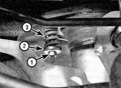
Figure 16.6. The connection unit of the exhaust system inlet pipe to the manifold, consisting of a nut (1), a spring cap (2) and a spring (3) (if you look from under the car)
Rear pipe
7. Loosen the rear pipe clamp ring bolts and remove the clamp from the flange joint.
8. Release the rear pipe from the corresponding rubber supports and remove it from the vehicle.
Complete system
9. Unscrew the two nuts securing the flange connection of the inlet pipe to the manifold and remove the spring caps and springs. Remove the bolts, then release the system from its rubber mounts and remove it from under the vehicle. Remove the wire mesh gasket from the manifold joint.
Heat shield
10. Heat shields are secured to the underbody of the vehicle using various nuts and bolts. Each screen can only be removed after removing the corresponding section of the exhaust system. If the screen is removed to gain access to components located behind it, in some cases it may be sufficient to remove the nuts and/or bolts and simply lower the screen without touching the exhaust system.
Installation
11. Each section is installed in the reverse order of removal, taking into account the following points:
- a) Remove all traces of corrosion from the flanges and replace all necessary gaskets.
- 6) Inspect the rubber mounts for signs of damage or deterioration and replace if necessary.
- c) Before assembling the spring-loaded joint, apply high-temperature grease to the mating surfaces of the joint.
- d) If the connection uses a clamping ring, apply exhaust system assembly paste to the flange connection to ensure gas-tightness of the joint. Tighten the clamp ring nuts evenly and gradually until the gap between the clamp sections is equal on both sides.
- d) Before tightening the exhaust system bolts/nuts, make sure that all rubber mounts are correctly positioned and there is sufficient clearance between the exhaust system and the underbody of the vehicle.
- e) Ensure that the oxygen sensor electrical connectors are properly connected and that the wiring is secured to the underbody with the appropriate clamps.