
Selection of bearing shells
1. Have the crankshaft inspected and measured by an engine overhauler. Specialists will be able to perform any regrinding / repair and select the appropriate liners for main and connecting rod bearings.
Installation
Note. When installing the crankshaft, use new cap/main bearing housing bolts.
2. If applicable, install oil jets in the bearing area of the cylinder block.
1.4L engines
3. Using a little grease, glue the top thrust washers to each side of the top of the #2 main bearing. Make sure the grease grooves on each thrust washer are facing out (away from the cylinder block).
4. Wipe clean the backs of the bearing shells and bearing mounting locations in the cylinder block/crankcase and main bearing housing/bearing caps.
5. Install the bushings in their original positions, making sure that the tab on each bushing fits into the groove in the cylinder block/crankcase and main bearing housing/bearing cap. Be careful not to touch the running surfaces of the bearing shells with your fingers. Note that the top and bottom bearing shells #2 and #4 have a groove (pic. 17.5).
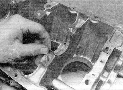
Pic. 17.5. Install grooved bushings for No. 2 and No. 4 bearings (engines 1.4 l)
6. Lubricate each bearing shell in the cylinder block/crankcase liberally with clean engine oil.
7. Install the key, and then install the oil pump drive sprocket and put the drive chain on the sprocket (pic. 17.7). Install the crankshaft in place so that the connecting rod journals No. 2 and 3 are in the TDC position; the connecting rod journals of cylinders No. 1 and 4 will be in the BDC position. This is the position ready to install the No. 1 piston. Check the crankshaft end play as described in paragraph 13.
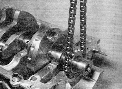
Pic. 17.7. Install the oil pump drive chain and sprocket (engines 1.4 l)
8. Thoroughly degrease mating surfaces of cylinder block/crankcase and main bearing housing. Apply a narrow bead of sealant to the surface of the main bearing housing mating with the cylinder block. Then spread the sealant into a thin layer (pic. 17.8).
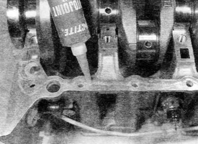
Pic. 17.8. Apply a thin coat of sealant to the mating surface of the cylinder block (engines 1.4 l)
9. Make sure that the dowel pins are in place. Then lubricate the lower bearing shells with clean engine oil. Install the main bearing housing to the cylinder block, making sure the lower bearings remain in the correct position.
10. Screw in bolts of fastening of the case of radical bearings and tighten them all only by force of a hand. Working in a spiral sequence, starting from the center bolts and moving outward, evenly and gradually tighten the bolts to the prescribed torque according to step 1 (pic. 17.10). Once all the bolts have been tightened according to the stage, working in the same sequence, use the socket and extension to tighten the bolts to the specified angle according to stage 2. It is recommended to use a protractor at this stage of tightening to ensure accuracy. In the absence of a goniometer, before tightening, apply white paint marks on the relative position of the bolt head and the main bearing housing; the markings can then be used to check that the bolt has rotated correctly during the tightening process.
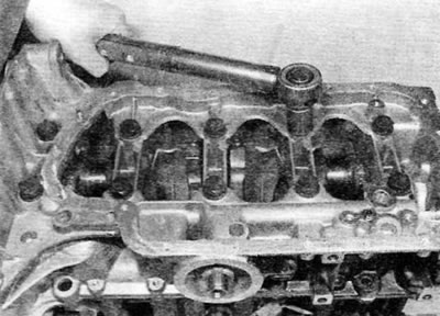
Pic. 17.10. Tighten the ten main bearing bolts to the specified torque (engines 1.4 l)
11. Screw all the smaller bolts securing the main bearing housing to the base of the cylinder block and tighten them to the prescribed torque. Make sure that the crankshaft turns freely.
12. Install the pistons and connecting rods to the crankshaft as described in paragraph 18.
13. After making sure that the drive chain is correctly placed on the sprocket, install the oil pump and oil pan as described in chapter 2A.
14. Install two new cuffs on the crankshaft as described in chapter 2A.
15. Install the flywheel as described in chapter 2A.
16. Install the cylinder head (if it was taken), as described in chapter 2A. Also install the crankshaft sprocket and timing belt (see chapter 2A).
Engines 1.6 l
17. Using a little grease, glue the top thrust washers to each side of the top of the #2 main bearing. Make sure the grease grooves on each thrust washer are facing out (away from the cylinder block) (pic. 17.17).
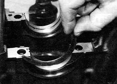
Pic. 17.17. Install thrust washers on both sides of the No. 2 main bearing with the oil grooves facing out (engines 1.6 l)
18. Install the liners in regular places, as described in paragraphs 4 and 5 (pic. 17.18). If new bearings are installed, use kerosene to remove all traces of protective grease from them. Wipe the earbuds dry with a lint-free cloth. Liberally coat each bearing shell in the cylinder block/crankcase and bearing cap with clean engine oil.
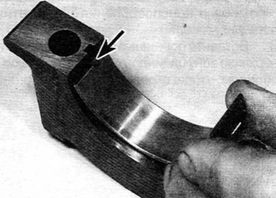
Pic. 17.18. When installing the bearing shell, make sure that the protrusion (marked with an arrow) was located in the corresponding cutout (engines 1.6 l)
19. Install the crankshaft in place so that the connecting rod necks No. 2 and 3 are in the TDC position; the connecting rod journals of cylinders No. 1 and 4 will be in the BDC position. This is the position ready to install piston No. 1. Check the crankshaft end play as described in paragraph 13.
20. Lubricate the lower bearing shells in the main bearing caps with clean engine oil. Make sure that the mounting protrusions on the inserts fit into the corresponding recesses in the covers.
21. Install the main bearing caps in their original position, orienting them correctly (the projections on the bearing shells and the recesses in the block and covers must be located on the same side).
22. Lightly lubricate the threads and the reverse side of the heads of the bolts securing the main bearing caps with engine oil, and then screw in the bolts. Working in a helical sequence, starting from the center bolts and moving outward, evenly and progressively tighten the bolts to the specified torque in step 1. angle according to stage 2. It is recommended to use a goniometer at this stage of tightening to ensure accuracy. In the absence of a goniometer, before tightening, apply white paint marks on the relative position of the bolt head and the main bearing housing; the markings can then be used to check that the bolt has rotated correctly during the tightening process.
23. Be convinced of freedom of turning of a cranked shaft.
24. Install the pistons and connecting rods to the crankshaft as described in paragraph 18.
25. Install the keyway into the groove on the crankshaft and install the oil pump drive sprocket. Install the drive chain to the sprocket.
26. Clean and dry the mating surfaces of the housing of the right (on the side of the timing belt) cuffs and cylinder block. Mark the depth of the cuff installation, and then use a large flat screwdriver to remove «old» cuff from the body.
27. Apply a bead of suitable sealant to the seal body mating surface and verify that the dowel pins are present. Install the cuff housing on the end of the crankshaft and then bring it to its original position on the cylinder block. Tighten the housing bolts securely.
28. Repeat steps 26 and 27 and install the left cuff housing (flywheel side).
29. Install new crankshaft seals as described in chapter 2A.
30. After making sure that the drive chain is correctly placed on the sprocket, install the oil pump and oil pan as described in chapter 2A.
31. Install the flywheel as described in chapter 2A.
32. Install the cylinder head (if it was taken). Also install the crankshaft sprocket and timing belt (see chapter 2A).