



Note: New big end nuts/bolts must be used during installation.
1. Please note that the following procedure is based on the premise that the cylinder liners (aluminum block engines) are located in their standard locations in the cylinder block/engine crankcase, as described in paragraph 11, and the crankshaft and main bearing housing/caps are installed.
2. Clean the backs of the bearing shells and the bearing mounting areas in the connecting rod and bearing cap.
3. Install the bearing shells into place, ensuring that the tab on each shell fits into the groove in the connecting rod and cap. Do not touch the working surface of the bearing shells with your fingers (figure 18.3).
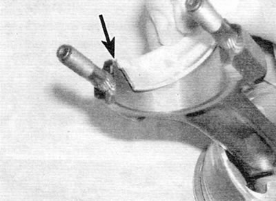
Figure 18.3. Make sure that the protrusion on the bearing shell (marked with an arrow) was correctly inserted into the cutout
4. Lubricate the cylinders, pistons and piston rings, and then insert each piston assembly with the connecting rod into the corresponding cylinder.
5. Begin assembly with cylinder #1. Make sure the piston ring joints are still positioned as described in paragraph 16, and then compress the rings using a piston ring compressor.
6. Insert the piston assembly with the connecting rod into the upper area of cylinder/liner No. 1 so that the arrow on the piston crown faces the end of the engine where the timing belt is located.
7. Once the piston is correctly positioned, use a wooden block or the handle of a hammer to lightly tap the piston crown and drive it into the cylinder/sleeve. The piston crown should be flush with the top of the cylinder/sleeve (figure 18.7).
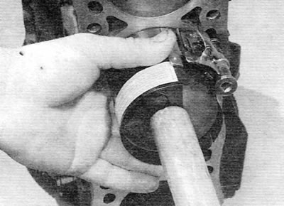
Figure 18.7. Insert the piston into the cylinder using the hammer handle
8. Check that the liners have not shifted from the correct position. Generously lubricate the crankpin and both bearings. Carefully, so as not to dirty the cylinder/liner surface, move the piston assembly with the connecting rod down until it fits onto the crankpin. Install the big end bearing cap, screw on the new nuts and tighten them by hand only at first (figure 18.8). Please note that surfaces with identification markings must be consistent (this means that the mounting projections of the bearing shells must be adjacent to each other).
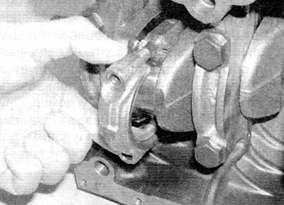
Figure 18.8. Install the big-end bearing cap, orienting it correctly, and tighten the new nuts
9. Tighten the bearing cap nuts evenly and gradually to the specified torque.
10. Once the bearing cap nuts are properly tightened, rotate the crankshaft. Make sure it rotates freely. When installing new components, some stiffness is acceptable, but there should be no binding or seizing.
11. Install the cylinder head and oil pump as described in chapter 2A.