
2. If there is a visible wear ridge on the top of any cylinder, it may be necessary to remove it with a scraper or special reamer to avoid damaging the piston during removal. The presence of such a ridge indicates increased cylinder wear.
3. Using quick dry paint, mark each connecting rod and connecting rod bearing cap on a flat machined surface with the appropriate cylinder number. If the engine has been disassembled before, pay attention to any identification marks previously applied (pic. 9.3). Keep in mind that cylinder #1 is at the end of the engine where the gearbox mates (flywheel).
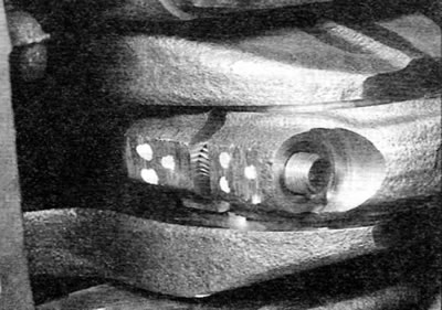
Pic. 9.3. Identification marks on the connecting rod and bearing cap (bearing #3 shown)
4. Rotate the crankshaft just enough to bring the No. 1 and No. 4 pistons to the BDC position (to bottom dead center).
5. Remove the nuts or bolts, as applicable, from the No. 1 connecting rod lower head bearing cap. Remove the cap and remove the lower bearing shell (pic. 9.5). If bearing shells are to be used further, tape the cover and bearing together with adhesive tape.
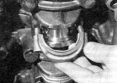
Pic. 9.5. Remove the connecting rod bearing shell and bearing cap
6. Tape the threaded ends of the connecting rod studs, if applicable, to prevent possible damage to the main journals (pic. 9.6).
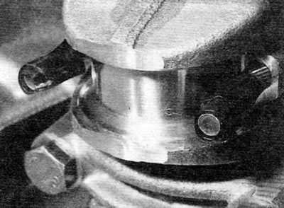
Pic. 9.6. Tape the threaded ends of the connecting rod studs to protect the crankshaft journals
7. Using a hammer handle, push the piston up along the cylinder and remove it over the top of the cylinder block. Remove the bearing shell, use adhesive tape to secure it to the connecting rod and put it in a safe place.
8. Install the connecting rod cap to the connecting rod and secure it with the nuts/bolts without tightening them. This will help keep the elements in the correct order.
9. Remove piston No. 4 in the same way.
10. Rotate the crankshaft 180°to bring pistons No. 2 and 3 to BDC (to bottom dead center), and remove them in the same way.