



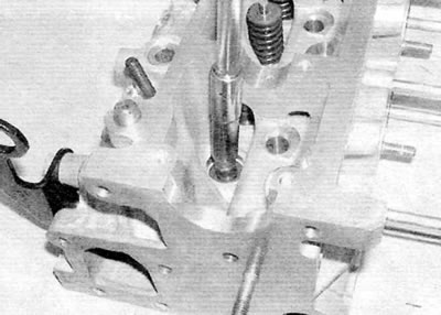
Figure 8.1 Using a suitable socket, press the new oil seal firmly onto the guide bushing
2. Lubricate the first valve stem and insert it into the guide bushing (figure 8.2).
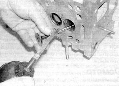
Figure 8.2. Lubricate the valve stem and insert it into the guide
3. Install the spring on the lower plate and then install the upper spring plate (figure 8.3, a, b).
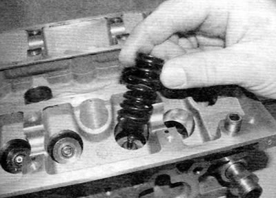
Figure 8.3, a. Install the valve spring...
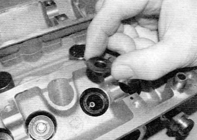
Figure 8.3, b....then install the upper plate on the spring
4. Compress the valve spring and insert the crackers into the groove on the valve stem (figure 8.4). Remove the spring compressor and repeat the procedure on the remaining valves. The valves should be installed according to their original position. When installing new valves, install them in accordance with their lapping order.
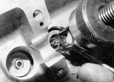
Figure 8.4. Compress the valve spring and insert the crackers into the recess on the valve stem
Tip: Use grease to hold the valve spring keepers on the valve stem when removing the spring compressor.
5. After installing all the valves, make sure the cylinder head is stable, take a hammer and lightly tap the end of each valve stem through an intermediate wooden block. This will allow the elements to take a stable position.
6. Install the camshaft, hydraulic lifters and valve levers (whichever is applicable), as described in chapter 2A.
7. Install all remaining components in the reverse order of removal. Install new seals or gaskets if necessary.
8. The cylinder head can then be installed as described in chapter 2A.