
Vehicles with diesel engine DK5ATE
Removing
1. Jack up the car, place it on jack stands.
2. Remove the mudguard of the engine compartment.
3. Drain gear oil
4. Remove the right drive shaft.
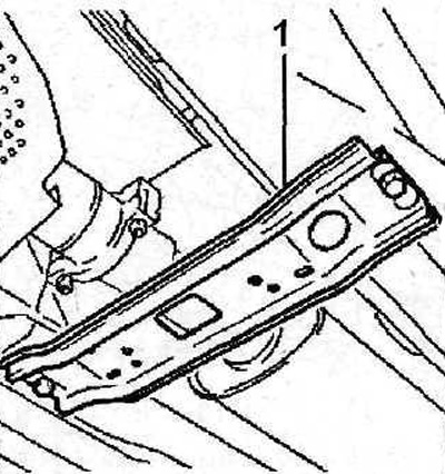
5. Remove downpipe 1 (see illustration).
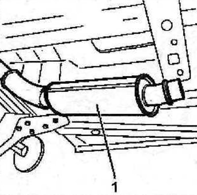
4.5 Remove downpipe 1
6. Disconnect the supply and return pipes 2 and 3 from the turbocharger (see illustration).
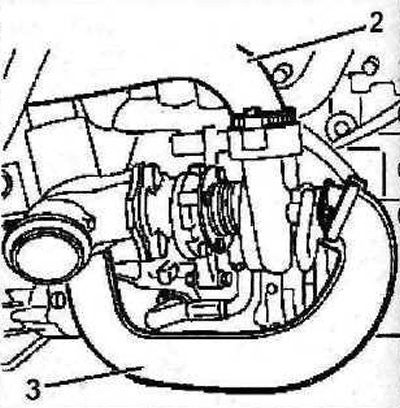
4.6 Disconnect supply and return lines 2 and 3 from the turbocharger
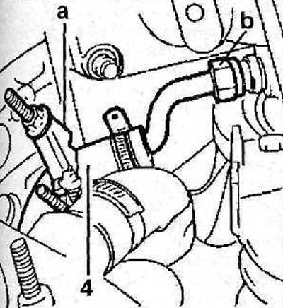
7. Remove heat shield 4 (see illustration).
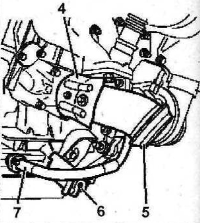
4.7 Remove heat shield 4
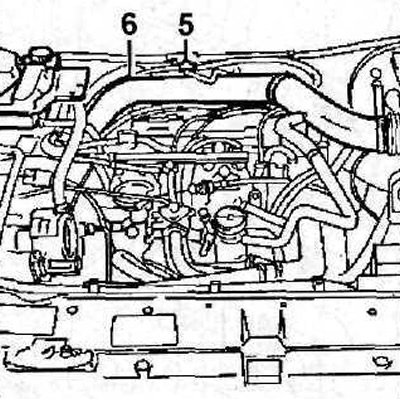
8. Disconnect the outlet pipe 5 from the turbocharger (see illustration 4.7). Tightening torque - 20 Nm.
9. Remove bracket 6 (see illustration 4.7). The tightening torque for the bracket mounting bolts is 20 Nm.
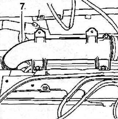
10. Disconnect the oil return line 7 from the cylinder block (see illustration 4.7).
11. Disconnect hose 8 from the turbocharger, unscrew nuts 9 and remove the turbocharger (see illustration). The tightening torque for the turbocharger mounting nuts is 25 Nm.
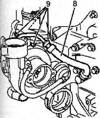
4.11 Disconnect hose 8 from the turbocharger, unscrew nuts 9 and remove the turbocharger
The turbocharger is installed in the reverse order of removal.
Attention. Nuts and fastening clamps, as well as oil seals and gaskets of oil lines must be replaced after each dismantling.
Vehicles with XU10J2TE gasoline engine
Removing
12. Jack up the car, place it on jack stands.
13. Remove connecting bracket 1 (see illustration).
4.13 Remove connecting bracket 1
14. Remove a collar of fastening of an exhaust pipe.
15. Disconnect oil return line 2 (see illustration).

4.15 Disconnect oil return line 2
16. Unscrew the lower bolt 3 fastening the heat-reflecting shield of the exhaust manifold (see illustration 4.15). The bolt tightening torque is 15 Nm.
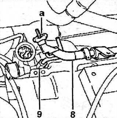
17. Clamp hose 4 with a suitable clamp, e.g «A», and disconnect the hose (see illustration).
4.17 Clamp the hose 4 with a suitable clamp, e.g «A», and disconnect the hose. The tightening torque of the hose fastening nut is 30 Nm
18. Move the reservoir of the power steering pump away from the place of work.
19. Remove the solenoid valve 5 of the exhaust gas recirculation system, and then disconnect the pipeline 6 from the turbocharger (see illustration).
4.19 Remove solenoid valve 5 of the exhaust gas recirculation system, and then disconnect pipe 6 from the turbocharger
20. Remove the exhaust manifold 7 together with the gasket (see illustration).
4.20 Remove the exhaust manifold with gasket
21. Plug the turbocharger inlet and outlet with suitable plugs.
22. Clamp hose 8 with a suitable clamp, e.g «A», and unscrew the nut 9 of its fastening (see illustration). Hose seals 8 must be replaced after each disassembly.
4.22 Clamp the hose with a suitable clamp, e.g «A», and unscrew the nut 9 of its fastening. The tightening torque of the nut is 30 Nm
23. Remove the exhaust manifold heat shield (see illustration).
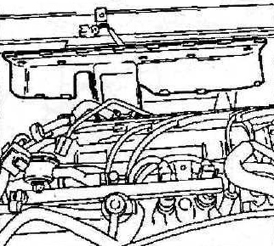
4.23 Remove the exhaust manifold heat shield
24. Unscrew the two top turbocharger mounting nuts.
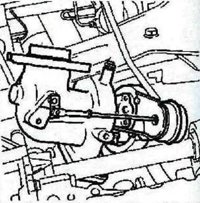
25. Unscrew the bolt 10 of the engine mount (see illustration).
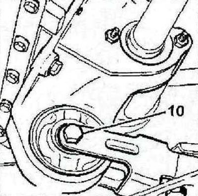
4.25 Unscrew the bolt 10 of the engine mount. Tightening torque - 50 Nm
26. Move the power block forward about 40 mm by inserting a block of wood between the differential and subframe.
27. Unscrew the mounting bolts and remove the supports 11 (see illustration).
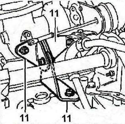
4.27 Unscrew the mounting bolts and remove the supports 11
28. Unscrew the two lower turbocharger fastening nuts and carefully remove the turbocharger (see illustration).
4.28 Carefully remove the turbocharger
29. Replace O-ring 12 (see illustration). Before installing, lubricate the new ring with LUBRITHERM G 200.
The turbocharger is installed in the reverse order of removal, taking into account the following:
30. The turbocharger fastening nuts must be replaced after each dismantling. Their tightening torque is 40 Nm.
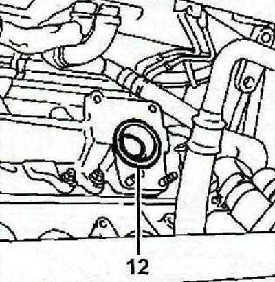
4.29 Replace O-ring 12
31. Tighten the bolts 13 and 14 of the supports 11, first by hand, and then with a force of 40 Nm (see illustration). Tighten bolts 13 first, then bolts 14.
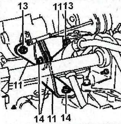
4.31 Tighten the bolts 13 and 14 of the supports 11 first by hand and then with a force of 40 Nm