
6. Check up a condition of springs and a conical notch of splines of a conducted disk. The diameter of the driven disk on all engines is the same (see illustration).
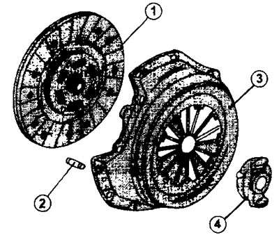
2.6 Clutch installed on engines with MLT5 gearbox
1 - clutch disc
2 - locating pin
3 - pressure plate
4 - clutch release bearing
7. Replace the driven disc if the friction linings are oily. They are not to be cleaned.
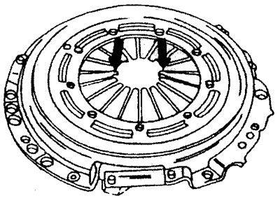
8. Check the thickness of the friction linings, as well as the condition of the pressure plate (see illustration).
2.8 Using a vernier caliper, check the thickness of the friction linings of the driven disk
If the residual lining thickness is less than 0.30 mm, then the driven disk should be replaced. The disc, the residual thickness of the friction linings of which is slightly larger than the specified size, is also subject to replacement.
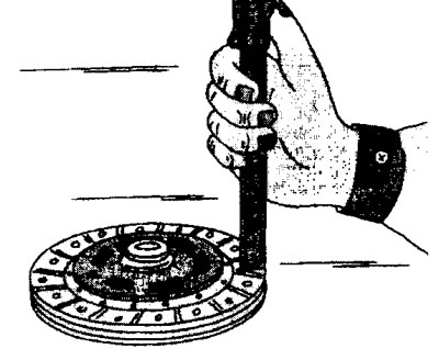
9. Check up beating of a conducted disk, slowly turning it and following an arrow of the indicator. If the indicator reading is only slightly above 0.8 mm, the disc can be straightened with some care. Otherwise, it must be replaced (see illustration).
2.9 Check the runout of the driven disk by slowly turning it and watching the indicator arrow
10. Check up a condition of vents of a conducted disk. If they are broken, then the disk must be replaced (see illustration).
2.10 Check the condition of the driven disk splines. If they are broken, then the disk must be replaced
11. Check up a pressure disk on absence of a curvature and deformation. Place a steel ruler on the working surface of the disc and measure the gap with a template. If the gap height is greater than 0.3 mm, then the pressure plate must be replaced (see illustration).
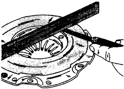
2.11 Check the pressure plate for distortion and deformation. Place a steel ruler on the working surface of the disc and measure the gap with a template
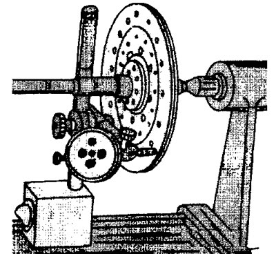
12. Check for flywheel runout by attaching a dial indicator as shown in the illustration and rotating the flywheel. Flywheel runout should not exceed 0.10 mm (see illustration).
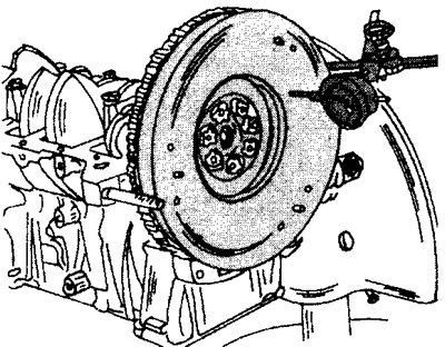
2.12 Check the runout of the flywheel by fixing the dial indicator as shown in the illustration and turning the flywheel
If it is necessary to remove the flywheel from the crankshaft, then during its subsequent installation, the old mounting bolts should be replaced with new ones. Tighten the bolts in a cross pattern. Before installing the flywheel, clean the surface of the flywheel on the crankshaft side, as well as the seating surface of the shaft.