



The fan is switched on and off by a temperature switch located at the bottom of the radiator. To quickly warm up the engine to an operating temperature of approximately 80°C, the cooling system is divided by a thermostat into a large and small cooling circuit. This temperature dependent regulator controls the flow of coolant. A wax filled bushing and a spring provide movement of both valve plates in the thermostat. During warm-up, at temperatures below 83°C, the thermostat valve shuts off the flow of coolant to the radiator. The bypass valve on the other side of the thermostat causes the coolant to immediately return to the water pump, from where it is re-entered into the engine. This small circuit ensures rapid warm-up of the engine, heating system, and also achievement of the engine operating temperature.
At temperatures between 85 and 100°C, the liquid partially enters the radiator, while the path to the water pump remains more or less open. This allows the cold coolant coming from the radiator to mix with the warm coolant before it enters the engine. This way the engine is not immediately exposed to cold coolant.
When the coolant temperature reaches 100°C, the main thermostat valve opens fully and the bypass valve closes. All coolant passes through the radiator, where it is continuously cooled.
To increase the coolant's efficiency during warm-up, the cooling system is pressurized to up to 1.0 bar. This pressure is maintained by a spring-loaded plate in the radiator cap. Due to the presence of pressure and the use of a frost-protective compound, the boiling point of the coolant increases. When the maximum pressure is exceeded, the shut-off plate in the cover opens and releases pressure in the system.
Over time, the anti-corrosion additive in the coolant becomes ineffective, so the coolant must be replaced regularly. On average, you should expect that replacement will need to be done every 3 years.
Additional information about the thermostat. Temperature switch 97) in Figure 281 is a sensor of the alarm that warns about unacceptable overheating of the engine. The switch (8) serves as a temperature indicator on the instrument panel.
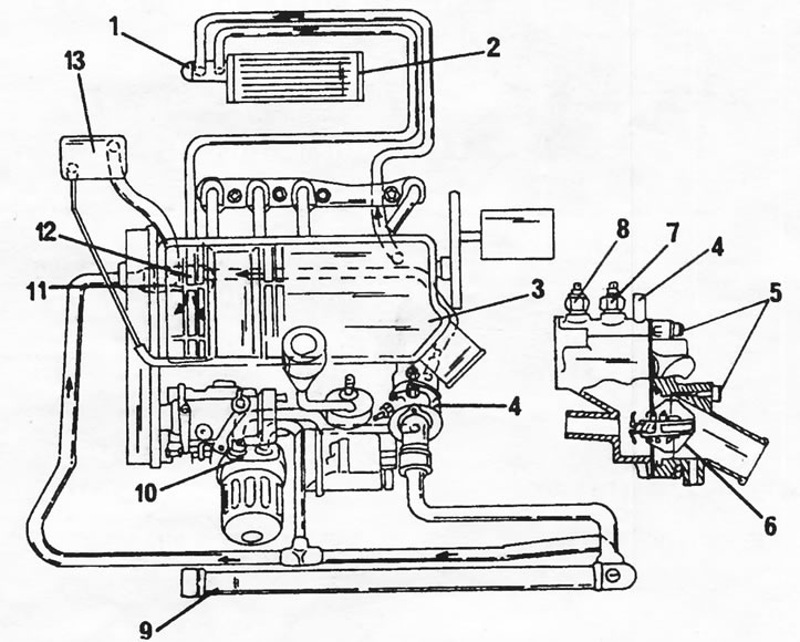
Figure 281. Cooling system diagram. 1. Heater switch; 2. Heater radiator; 3. Cylinder head ventilation; 4. Cooling system outlet fitting; 5. Air release valve; 6. Thermostat; 7. Temperature signal switch; 8. Temperature switch; 9. Radiator; 10. Oil radiator; 11. Water pump; 12. Cooling system inlet fitting with fuel heating element; 13. Expansion tank
Text taken from the website PeugeotBook.ru
The cooling system also includes an oil radiator (10), installed between the oil filter and the cylinder block and connected to the cooling system by two hoses. A heating element for heating diesel fuel is located at the inlet fitting of the cooling system. It warms up the fuel when cold and ensures easy engine starting.