



2. Remove clamp 1 (see illustration).
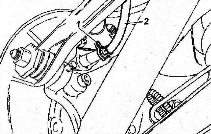
7.2 Remove clamp 1
3. Disconnect the end of the cable 2 at point 3 (see illustration).
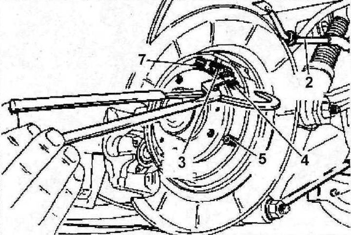
7.3 Disconnect the end of the cable 2 at point 3
4. Disconnect cable 2 from the support shield (see illustration 7.3).
5. Disconnect the upper return spring 4, and then the pins 5 securing the pads 6 (see illustration 7.3).
6. Remove the mechanism 7 for releasing the parking brake pads from the disc (see illustration 7.3).
7. Remove the lower return spring 8 using needle-nose pliers (see illustration)
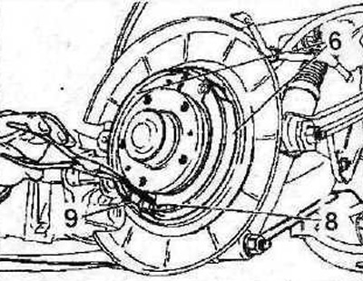
7.7 Remove the lower return spring 8 using needle-nose pliers
8. Remove the expansion bar 9 (see illustration 7.7).
9. Remove the parking brake shoes 6 (see illustration 7.7).
The parking brake shoes are installed in the reverse order of removal, taking into account the following:
10. Clean the surface of the support board 10 (see illustration).
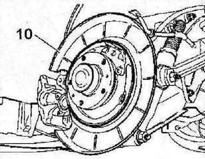
7.10 Clean the surface of the support shield 10
11. Adjust the position of the expansion bar 9 by tightening or loosening the adjusting gear 11 (see illustration).
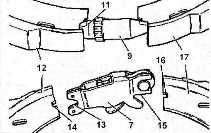
7.11 Adjust the position of the expansion bar 9 by tightening or loosening the adjusting gear 11
12. When installing the brake shoe release mechanism, insert fork 13 into recess 14 of shoe 12, and fork 15 into recess 16 of shoe 17 (see illustration 7.11).
13. Adjust the parking brake cables.