



Warning: Renew BOTH sets of rear brake shoes at the same time - NEVER renew the shoes on only one wheel, as uneven braking may result. Note that the dust created by wear of the shoes may contain asbestos, which is a health hazard. Never blow it out with compressed air and don't inhale any of it. An approved filtering mask should be worn when working on the brakes. DO NOT use petrol or petroleum-based solvents to clean brake parts; use brake cleaner or methylated spirit only.
1. Remove the rear brake drums (Section 9).
2. Working on one side of the vehicle, brush the dirt and dust from the brake backplate and drum. Do not inhale the dust, as it may be a health hazard.
3. Note the position of each shoe and the location of the return and steady springs (see illustration).
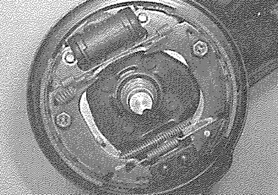
6.3. Rear brake shoes and components. Note the locations of the springs
4. Remove the shoe hoid-down springs. Use pliers to depress the outer spring cups and turn them through 90° (see illustrations).
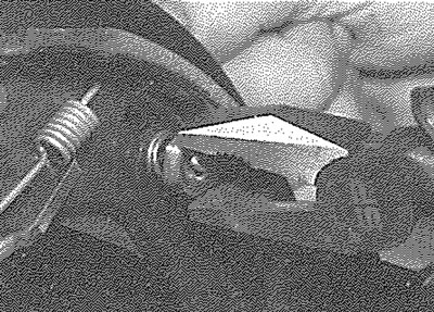
6.4a. Use pliers...
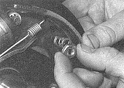
6.4b.... to remove the outer hold-down spring cups
5. Recover the springs and cups and remove the spring retainer pins from the backplate.
6. Carefully pull the leading brake shoe forwards from the backplate and using a suitable pair of pliers, unhook and remove the lower return spring (see illustrations).
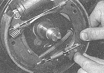
6.6a. Pull the leading brake shoe forwards...
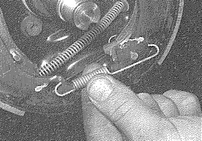
6.6b.... and remove the lower return spring
7. Disengage the lower ends of the shoes from the bottom anchor and pull the upper ends of the shoes from the wheel cylinder, then withdraw the shoe assembly and unhook the handbrake cable from the lever on the trailing brake shoe (see illustration).
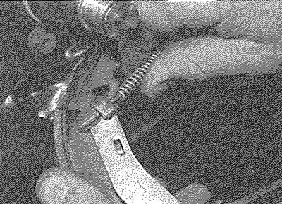
6.7. Unhooking the handbrake cable from the lever on the trailing shoe
8. If necessary, position a rubber band or a cable-tie over the wheel cylinder, to prevent the pistons from being ejected (see illustration). If there is any evidence of fluid leakage from the wheel cylinder, renew it or overhaul it as described in Section 12.
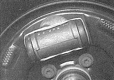
6.8. Rubber band positioned over wheel cylinder to retain pistons
9. Unhook the upper return spring from the shoes and unhook the adjuster strut spring.
10. Working on the leading brake shoe, prise the adjuster lever retaining plate over the pivot pin on the adjuster lever, then pull the adjuster lever forwards to allow the adjuster strut to be removed (see illustrations).
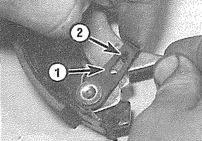
6.10a. Prise the retaining plate (1) over the pivot pin (2)...
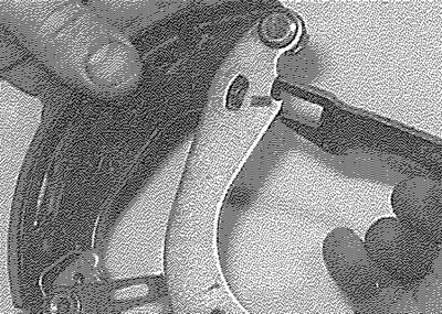
6.10b.... and remove the adjuster strut
11. Transfer the handbrake and automatic adjuster levers to the new shoes, as required (prise off the spring clips to remove the levers) (see illustration). Note that the levers and strut on each rear wheel are different and that the leading and trailing shoes are fitted with different grade linings. New shoes will be supplied complete with the adjuster retaining plate riveted to the leading shoe.
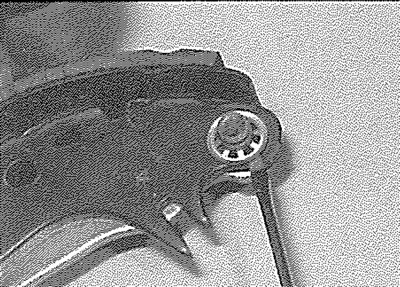
6.11. Prising off the spring clip to remove the adjuster lever from the trailing shoe
12. Place the shoes on the bench in their correct positions and iay the adjuster strut in position.
13. With the adjuster strut engaged with the leading shoe, push the adjuster lever back towards the shoe and clip the adjuster lever retaining plate over the pivot pin on the adjuster lever.
14. Fit the adjuster strut spring between the trailing shoe and the adjuster strut (see illustration), but do not fully engage the adjuster strut with the trailing shoe at this stage.
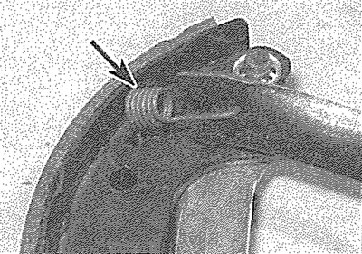
6.14. Fit the adjuster strut spring (arrowed) between the shoe and the adjuster strut
15. Fit the upper return spring to the shoes, then carefully manipulate the adjuster strut into position to engage it with the slot in the trailing shoe (see illustrations).
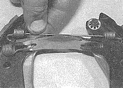
6.15a. Fit the upper return spring to the shoes...
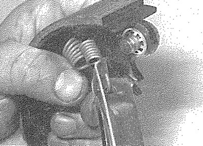
6.15b.... then engage the adjuster strut
16. Apply copper-based brake grease sparingly to the shoe contact areas of the brake backplate. Where applicable, remove the rubber band or cable tie from the wheel cylinder (see illustration).
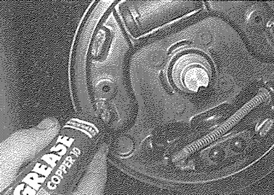
6.16. Apply copper-based brake grease to the shoe contact areas
17. Offer the shoes into position and reconnect the handbrake cable to the handbrake lever on the trailing shoe.
18. Position the shoes on the backplate and lever the upper ends of the shoes apart to engage them with the wheel cylinder.
19. Carefully refit the lower return spring to the shoes (see illustration), then lever the lower ends of the shoes apart to engage them with the lower anchor.
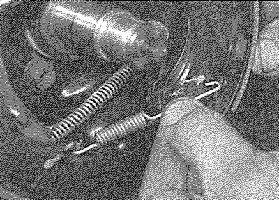
6.19. Refitting the lower return spring
20. Insert the steady spring retainer pins in the backplate and through the holes in the shoes, then fit the hold-down springs and the cups.
21. Move the serrated automatic adjuster lever quadrant against the spring tension, to set the shoes at their minimum diameter.
22. Check that the handbrake lever on the trailing brake shoe is positioned with the lug on the edge of the shoe web and not behind the shoe.
23. Repeat the procedure on the remaining side of the vehicle, then refit the brake drums as described in Section 9.
24. On completion, check the handbrake adjustment as described in Chapter 1A or 1B.