



Note: Before starting work, refer to the warning at the beginning of Section 6 concerning the dangers of asbestos dust.
Note: A new rear hub nut and dust cap must be used on refitting.
Removal
1. Chock the front wheels then jack up the rear of the vehicle and support it on axle stands (see "Jacking and vehicle support"). Remove the appropriate rear roadwheel.
2. Using a hammer and a large flat-bladed screwdriver, carefully tap and prise the dust cap out of the centre of the brake drum. Discard the cap - a new one must be used on refitting.
3. Using a hammer and a suitable cold chisel or punch, relieve the staking on the driveshaft nut.
Warning: Wear suitable eye protection.
4. Using a socket and long bar, slacken and remove the rear hub nut and withdraw the thrustwasher (see illustrations). Discard the hub nut - a new nut must be used on refitting.
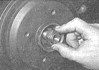
9.4a. Remove the hub nut...
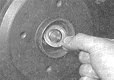
9.4b.... and withdraw the thrustwasher
5. It should now be possible to withdraw the brake drum assembly from the stub axle by hand (see illustration). It may be difficult to remove the drum, due to the tightness of the hub bearing on the stub axle, or due to the brake shoes binding on the inner circumference of the drum. If the bearing is tight, tap the periphery of the drum using a hide or plastic mallet, or use a universal puller, secured to the drum with the wheel bolts, to pull it off. If the brake shoes are binding, first check that the handbrake is fully released, then proceed as follows.
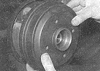
9.5. Withdrawing the brake drum
6. Insert a screwdriver through one of the wheel bolt holes in the brake drum, so that it contacts the handbrake shoe adjuster lever on the leading brake shoe. Push the lever to release the ratchet until the brake shoes are fully retracted (see illustration). The brake drum can now be withdrawn.
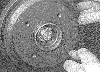
9.6. Using a screwdriver to release the shoe adjuster mechanism and retract the shoes
Inspection
Note: If either drum requires renewal, BOTH should be renewed at the same time, to ensure even and consistent braking. New brake shoes should also be fitted.
Information copied from the resource (www.PEUGEOTBOOK.ru)
7. Working carefully, remove all traces of brake dust from the drum, but avoid inhaling the dust, as it is a health hazard.
8. Clean the outside of the drum and check it for obvious signs of wear or damage, such as cracks around the roadwheel bolt holes; renew the drum if necessary.
9. Carefully examine the inside of the drum. Light scoring of the friction surface is normal, but if heavy scoring is found, the drum must be renewed. It is usual to find a lip on the drum's inboard edge which consists of a mixture of rust and brake dust; this should be scraped away, to leave a smooth surface which can be polished with fine (120- to 150-grade) emery paper, if, however, the lip is due to the friction surface being recessed by excessive wear, then the drum must be renewed.
10. If the drum is thought to be excessively worn, or oval, its internal diameter must be measured at several points using an internal micrometer. Take measurements in pairs, the second at right-angles to the first and compare the two, to check for signs of ovality. Provided that it does not enlarge the drum to beyond the specified maximum diameter, it may be possible to have the drum refinished by skimming or grinding; if this is not possible, the drums on both sides must be renewed. Note that if the drum is to be skimmed, BOTH drums must be refinished, to maintain a consistent internal diameter on both sides.
11. Check the condition of the oil seal on the stub axle and renew if necessary. To renew the oil seal, simply prise the old seal from the stub axle, then push the new seal into position until it is seated on the spacer. At the same time, check the condition of the oil seal seating ring in the rear of the drum and if any signs of wear or damage are present, renew the ring (if the surface of the ring is damaged, this is likely to quickly result in damage to the oil seal).
Refitting
12. If a new brake drum is to be installed, use a suitable solvent to remove any preservative coating that may have been applied to its internal friction surfaces. Note that it may also be necessary to shorten the adjuster strut length, by rotating the strut wheel, to allow the drum to pass over the brake shoes.
13. Ensure that the handbrake lever stop peg is correctly repositioned against the edge of the brake shoe web (see illustration), then apply a smear of clean engine oil to the stub axle and slide on the drum assembly.
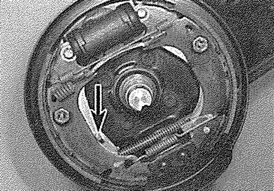
9.13. Ensure that the handbrake lever stop peg (arrowed) is positioned against the edge of the shoe web
14. Fit the thrustwasher and new hub nut and tighten the hub nut to the specified torque. Stake the nut firmly into the groove on the stub axle, to secure it in position (see illustrations).
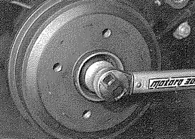
9.14a. Tighten the hub nut to the specified torque...
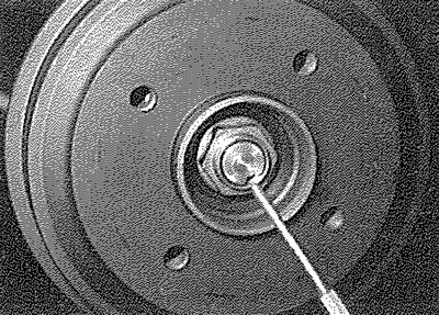
9.14b.... then stake the nut in position
15. Tap the new dust cover into place in the centre of the brake drum.
16. Depress the footbrake several times to operate the self-adjusting mechanism.
17. Repeat the above procedure on the remaining rear brake assembly (where necessary), then check and, if necessary, adjust the handbrake cable as described in Chapter 1A or 1B.
18. On completion, refit the roadwheel, then lower the vehicle to the ground and tighten the roadwheel bolts to the specified torque.