



Table of contents: Bendix caliper 🠇 ATE caliper 🠇
Warning: Renew BOTH sets of front brake pads at the same time - NEVER renew the pads on only one wheel, as uneven braking may result. Note that the dust created by wear of the pads may contain asbestos, which is a health hazard. Never blow it out with compressed air and don't inhale any of it. An approved filtering mask should be worn when working on the brakes. DO NOT use petrol or petroleum-based solvents to clean brake parts; use brake cleaner or methylated spirit only.
1. Chock the rear wheels then jack up the front of the vehicle and support it on axle stands (see "Jacking and vehicle support"). Remove the front roadwheels.
2. Trace the brake pad wear sensor wiring back from the pads and disconnect it from the wiring connector (see illustration). Note the routing of the wiring and free it from any relevant retaining clips.
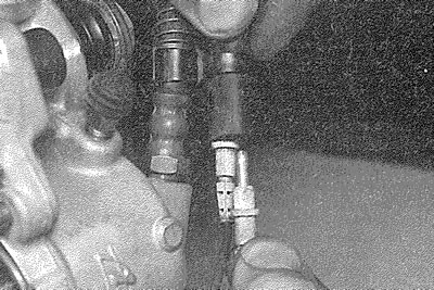
4.2. Disconnecting the brake pad wear sensor wiring - ATE caliper
3. Push the piston into its bore by pulling the caliper outwards.
4. There are different types of front brake caliper fitted to the models covered in this manual. Identify the relevant caliper by reference to the accompanying illustrations (the manufacturer's name is usually stamped on part of the caliper, in any case), then proceed as described under the relevant subheading. The procedure for vented discs is given in Section 27.
Bendix caliper
5. Using pliers, extract the small spring clip from the pad retaining plate and then slide the plate out of the caliper (it will probably be necessary to tap the plate from the caliper) (see illustrations).
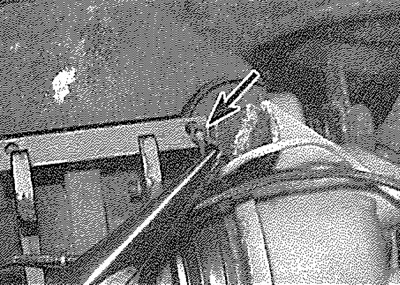
4.5a. Extract the spring clip (arrowed)...
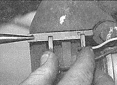
4.5b.... and slide out the pad retaining plate - Bendix caliper
6. Withdraw the pads from the caliper (see illustrations), then make a note of the correct fitted position of each anti-rattle spring and remove the spring from each pad (where applicable, unclip the pad wear sensor wiring). It may be necessary to push the inboard pad back against the piston, to retract the piston into its bore, before the pad can be removed.
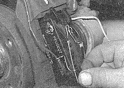
4.6a. Withdraw the outer...
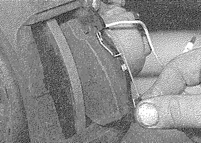
4.6b.... and inner pads - Bendix caliper
7. First measure the thickness of each brake pad's friction material. If either pad is worn at any point to the specified minimum thickness or less, all four pads must be renewed. Also, the pads should be renewed if any are fouled with oil or grease; there is no satisfactory way of degreasing friction material, once contaminated. If any of the brake pads are worn unevenly, or are fouled with oil or grease, trace and rectify the cause before reassembly. New brake pads and spring kits are available from Peugeot dealers.
8. If the brake pads are still serviceable, carefully clean them using a clean, fine wire brush or similar, paying particular attention to the sides and back of the metal backing. Clean out the grooves in the friction material and pick out any large embedded particles of dirt or debris. Carefully clean the pad locations in the caliper body/mounting bracket.
9. Prior to fitting the pads, check that the guide pins are free to slide easily in the caliper body/mounting bracket and check that the rubber guide pin gaiters are undamaged. Brush the dust and dirt from the caliper and piston, but do not inhale it, as it is injurious to health. Inspect the dust seal around the piston for damage and the piston for evidence of fluid leaks, corrosion or damage. If attention to any of these components is necessary, refer to Section 10.
10. If new brake pads are to be fitted, the caliper piston must be pushed back into the cylinder to make room for them. Either use a G-clamp or similar tool, or use suitable pieces of wood as levers. Provided that the master cylinder reservoir has not been overfilled with hydraulic fluid, there should be no spillage, but keep a careful watch on the fluid level while retracting the piston. If the fluid level rises above the "MAX" level line at any time, the surplus should be syphoned off or ejected via a plastic tube connected to the bleed screw (see Section 2).
Warning: Do not syphon the fluid by mouth, as it is poisonous; use a syringe or an old poultry baster.
11. Apply a little copper-based brake grease to the pad backing plates, but take great care not to allow any grease onto the pad friction linings.
12. Fit the anti-rattle springs to the pads, so that when the pads are installed in the caliper, the spring end will be located at the opposite end of the pad in relation to the pad retaining plate.
13. Locate the pads in the caliper, ensuring that the friction material of each pad is against the brake disc and check that the anti-rattle spring ends are at the opposite end of the pad to which the retaining plate is to be inserted.
14. Slide the retaining plate into place and install the new small spring clip at its inner end. It may be necessary to file an entry chamfer on the edge of the retaining plate, to enable it to be fitted without difficulty.
15. Reconnect the brake pad wear sensor wiring connectors, ensuring that the outer wire is correctly routed through the anti-rattle spring loops and that both wires pass through the loop of the bleed screw cap (see illustration).
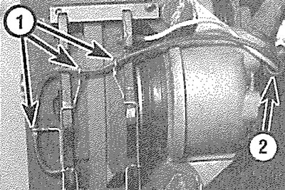
4.15. Brake pad wear sensor wiring is routed through anti-rattle springs (1) and bleed screw cap (2)
16. Depress the brake pedal repeatedly, until the pads are pressed into firm contact with the brake disc and normal (non-assisted) pedal pressure is restored.
17. Repeat the above procedure on the remaining front brake caliper.
18. Refit the roadwheels, then lower the vehicle to the ground and tighten the roadwheel bolts to the specified torque.
19. Check the hydraulic fluid level as described in "Weekly checks".
ATE caliper
20. Note the location and orientation of the pad anti-rattle spring (note the routing of the brake pad wear sensor wiring through the anti-rattle spring), then remove the pad retaining pins by tapping them from the caliper using a suitable pin-punch. Note that the pad retaining spring will be released as the pins are removed (see illustrations).
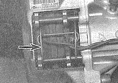
4.20a. Note the orientation of the pad anti-rattle spring (arrowed) - ATE caliper
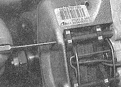
4.20b. Free the pad retaining pins from the caliper using a pin-punch...
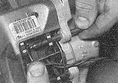
4.20c.... then withdraw the upper...
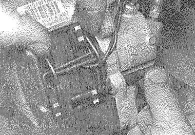
4.20d.... and lower pins - ATE caliper
21. Withdraw the pad retaining spring.
22. Withdraw the pads from the caliper. It may be necessary to push the inboard pad back against the piston, to retract the piston into its bore, before the pad can be removed (see illustrations).
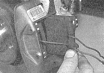
4.22a. Withdraw the inner...
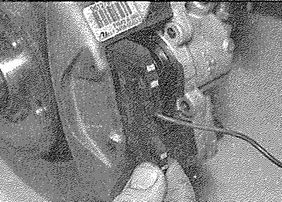
4.22b.... and outer brake pads - ATE caliper
23. Proceed as described in paragraphs 7 to 11 inclusive.
24. Slide the pads into position in the caliper, ensuring that the friction material of each pad is against the brake disc.
25. Locate the anti-rattle spring on the pads, as noted before removal and ensure that the pad wear sensor wiring is correctly routed through the spring (see illustration).
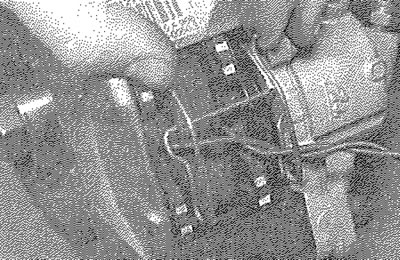
4.25. Ensure that the pad wear sensor wiring is correctly routed through the spring - ATE caliper
26. Fit the upper pad retaining pin, ensuring that the top arms of the pad retaining spring locate behind the pin, then tap the pin into position in the caliper.
27. Refit the lower pad retaining pin, ensuring that it passes through the anti-rattle spring, then tap the pin into position in the caiiper (see illustration).
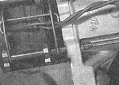
4.27. Tapping the lower pad retaining pin into position - ATE caliper
28. Reconnect the brake pad wear sensor wiring connectors, ensuring that the wiring is correctly routed.
29. Proceed as described in paragraphs 16 to 19 inclusive.