
Note. Although some modern friction materials may not contain asbestos, it is still safer to assume that asbestos is present and take appropriate precautions.
Attention! Clutch wear dust deposited on clutch elements may contain asbestos, which is hazardous to health. DO NOT blow it out with compressed air, as this could cause it to be inhaled. DO NOT use gasoline or petroleum-based solvents to remove dust. Use a brake cleaner or denatured alcohol to wash the dust into a suitable container. After wiping the clutch elements with a clean rag, place the dirty rag and cleaning agent in an appropriately labeled sealed container.
Removing
1. If you are not going to remove the entire engine assembly with gearbox from the car and separate it for overhaul (see relevant part chapter 2), the clutch can be reached after removing the gearbox, as described in chapter 7.
2. Before disassembling the clutch, take a piece of chalk or a marker and mark the position of the clutch housing relative to the flywheel.
3. Working in a criss-cross pattern, loosen the clutch housing bolts half a turn at a time until the spring force is sufficiently weakened that the bolts can be removed by hand.
4. Remove the clutch cover assembly with the pressure plate from the locating pins and behind it remove the driven disc, noting for yourself how it is installed (pic. 4.4).
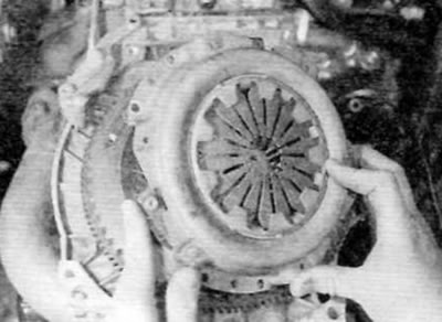
Pic. 4.4, a. Remove the clutch cover from the dowel pins...
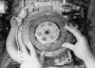
Pic. 4.4b....then remove the driven disk, noting how it is installed
Inspection
Note: Since the removal and installation of clutch elements takes a significant amount of time, it is common practice to replace the driven plate, pressure plate assembly and clutch release bearing as a single set, even if only one of them is actually worn out and requires replacement. Clutch replacement is recommended as a preventative measure that can be taken when the engine and/or transmission has been removed for any other reason.
5. Remove the clutch assembly.
6. When cleaning clutch elements, first read the warning given at the beginning of this paragraph. Remove dust using a clean dry cloth. Work in a well ventilated area.
7. Check the drive plate surfaces for signs of wear, damage, or oil contamination. If the friction linings are cracked, burnt, scratched or otherwise damaged, or the driven plate is contaminated with oil or grease (seen in shiny black spots), the disk should be replaced.
8. If the friction material is still serviceable, check that the disc hub splines are not worn, the torsion springs are in good condition and secure, and all rivets are tight. If there is wear or damage, the driven disk must be replaced.
9. If the friction material is contaminated with oil, this may be due to oil leakage through the left crankshaft collar, through the joint between the engine pan and cylinder block, or from the gearbox input shaft. Before installing a new driven disk, replace the seal or restore the tightness of the corresponding joint, as described in the relevant part chapter 2 or in chapter 7.
10. Check clutch cover/pressure plate assembly for obvious signs of wear or damage; shake it to check for loose rivets, worn or damaged diaphragm spring support rings. Check that the plates connecting the pressure plate to the casing do not show signs of overheating (such as color change to dark yellow or blue). If the diaphragm spring pins show signs of wear or damage, or if spring force is in doubt, the pressure plate assembly should be replaced
11. Inspect the machined working surfaces of the pressure plate and flywheel; they must be clean, completely flat, free from scratches or burrs. If they are discolored due to overheating or show cracks, the disc should be replaced - although minor damage of this nature can sometimes be repaired by buffing with sandpaper.
12. Check that the contact side of the clutch release bearing rotates smoothly and easily, without noise or jamming. Also check that the surface itself is smooth and unworn, free of cracks, pitting or burrs. If there is any doubt about the condition, the bearing should be replaced.
Installation
13. When assembling, make sure that the friction surfaces of the flywheel and pressure plate are absolutely clean, smooth and free of oil. Use a solvent to remove protective grease from new elements.
14. Establish a conducted disk so that its nave with springs was turned aside from a flywheel. The disc may have a label indicating. how should it be installed (pic. 4.14).
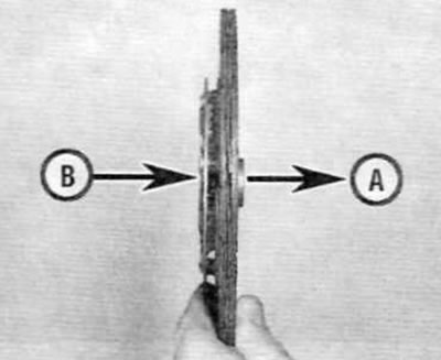
Pic. 4.14. Install the driven disc so that its spring-loaded hub (IN) facing away from the flywheel (A)
15. Install the clutch cover assembly with the pressure plate, focusing on the three dowel pins and aligning the marks made during disassembly (if the original node is reused). Screw in the pressure plate assembly mounting bolts, but tighten them only by hand so that the driven plate can be moved.
16. Now you should center the driven disk so that when installing the gearbox, its input shaft enters the splined hole in the center of the disk.
17. A screwdriver or other long rod can be used to center the driven disk. Insert a tool through the hole in the driven plate into the hole in the crankshaft centering bearing and move the driven plate until it is aligned with the hole in the end of the crankshaft. Alternatively, you can use a clutch centering tool available from many auto parts stores (pic. 4.17)

Pic. 4.17. Center the driven disc using the centering tool
Advice. The clutch alignment tool can be made independently from a piece of metal bar or wooden rod, which is tightly inserted into the hole on the end of the crankshaft. In order to ensure that the diameter of the slotted hole of the driven disk, wrap the required amount of insulating tape around the rod.
18. When the driven plate is centered, evenly, working in a cross sequence, tighten the bolts securing the clutch cover assembly with the pressure plate to the prescribed torque.
19. Apply a thin layer of molybdenum disulphide grease (Peugeot/Citroen recommends the use of Molykote BR2 Plus, available from your dealer) on the splines of the driven disk and the input shaft of the gearbox, as well as in the hole in the clutch release bearing and on the shaft of the clutch release fork.
20. Install the gearbox as described in chapter 7.