



Table of contents: Removal 🠇 Installation 🠇
Removal
1. Fully apply the parking brake, raise the front of the vehicle and support it securely (see "Lifting and installing the car on supports").
2. Drain the transmission oil as described in paragraph 2. Then screw in the drain plug and the filler/inspection hole plug and tighten them to the specified torque.
3. Remove the air filter and air intake duct as described in the relevant section chapter 4. On D9B diesel engines, also remove the air distribution housing as described in chapter 4A.
4. Remove the battery, battery tray and backing plate as described in chapter 5A.
5. Remove both axle shafts as described in chapter 8.
6. Remove the starter as described in chapter 5A.
7. Disconnect the clutch cable end from the release fork/lever (see chapter 6). Press on the tabs and release the cable housing from the bracket on the gearbox.
8. Disconnect the electrical connector of the reverse light switch, TDC sensor and speedometer drive. Remove the nuts/bolts and disconnect the grounding straps from the gearbox housing (figure 7.8, a, b). If necessary, disconnect the electrical connectors of the various additional switches/sensors, release the wiring harness from the clamps and position it away from the transmission.
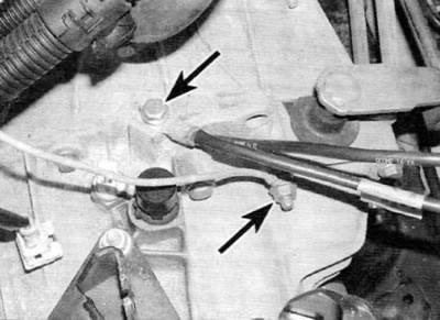
Figure 7.8, a. Unscrew the nut, unscrew the bolt (marked with arrows) and disconnect the ground wires from the gearbox (mA5 gearbox)
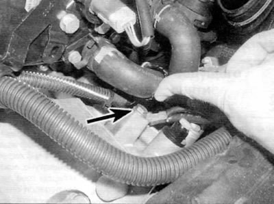
Figure 7.8, b. Unscrew the bolt (marked with an arrow) and disconnect the ground wire from the gearbox (vEZ/5 and VE4/5 gearboxes)
9. On the MA5 gearbox, unscrew the bolt securing the exhaust downpipe to the corresponding support bracket on the gearbox.
10. On MA5 gearboxes before 1998, unscrew the nut (with washer), and then remove the shaft that secures the gear selector rod to the gear shift lever on the gearbox. Disengage the linkage from the gear shift lever on the transmission. On all other transmissions, use a flat-head screwdriver to carefully pry the shift rod ball joints away from the corresponding levers on the transmission. Position the rods away from the gearbox.
11. On models with power steering, remove the nuts and bolts and release the power steering line support brackets from the transmission. Place the pipe away from the box to avoid damage during removal.
12. Unscrew the bolt and remove the lower flywheel cover (if applicable) from the gearbox.
13. On gearboxes BE3/5 and BE4/5, remove the speedometer drive housing from the gearbox as described in paragraph 6.
14. Place a jack with a wooden block on its head under the engine to relieve the load on its supports. Alternatively, attach a pair of lifting eyes to the engine and remove the weight from the engine mounts using a lifting device or engine support beam.
15. Place a jack with a wooden block on the head under the gearbox and raise the jack enough to support the weight of the gearbox.
16. Loosen the nut and remove the bolt securing the rear engine/gearbox mount clamp to the bracket on the subframe.
17. Remove the center nut (with washer) on the left engine/gearbox mount. Remove the two bolts/nuts securing the support to the support bracket and remove the rubber support.
18. On the MA5 gearbox, unscrew the three nuts and remove the support plate from the top of the gearbox.
19. On BE3/5 and BE4/5 gearboxes, remove the washer and spacer from the support stud, and then unscrew the stud from the top of the gearbox housing. Remove the large spacer plate from the support stud.0 After ensuring that the jack supports the weight of the transmission, remove the remaining transmission case to engine mounting bolts. Mark the installation position of each bolt and corresponding brackets when removed so that this information can be used during installation. Make a final check that all components are disconnected and positioned away from the gearbox so as not to interfere with removal.
21. Once the bolts are removed, move the trolley jack with the transmission to the left to remove it from the locating pins, then lift the differential end of the transmission up to unhook it from the subframe.
Warning. Use extreme caution to avoid excessive deformation of exhaust system components or damage to the radiator when moving the engine. On models equipped with air conditioning, care must also be taken to ensure that the accessory drive belt pulleys do not damage the refrigerant lines on the right side of the engine compartment.
22. Once the gearbox is free, lower the jack and remove the gearbox from under the vehicle. Remove the dowel pins from the transmission or engine if they are loose and store them in a safe place.
Installation
23. The gearbox is installed in the reverse order of removal, taking into account the following points:
- a) Apply a small amount of high temperature grease (peugeot/Citroen recommends using Molykote BR9 plus lubricant, which can be purchased from your dealer) on the splines of the primary shaft of the gearbox. Do not apply too much grease as there is a risk of grease getting on the clutch disc.
- b) Before installation, install the dowel pins properly.
- c) On BE3/5 and BE4/5 gearboxes, before installing the stud of the left support of the power unit on the gearbox, apply a compound to the thread locking compound of the stud. Tighten the stud to the specified torque.
- d) Tighten all nuts and bolts to the specified torque (if specified).
- d) Replace the axle shaft seals (paragraph 5), and then install the axle shafts (see chapter 8).
- e) Finally, fill the gearbox with the prescribed oil in the specified quantity as described in paragraph 2.