



Note: Refer to the warnings about the dangers of asbestos dust given at the beginning of paragraph 4.
Removal
1. If you are not going to remove the engine and gearbox assembly from the vehicle and separate it for major repairs (see the relevant section chapter 2), then the clutch release mechanism can be reached after removing only the gearbox, as described in chapter 7.
2. Different release mechanisms may be used depending on the type of gearbox. For information on identifying the transmission type, please refer to chapter 7, and then continue as described below under the appropriate subheading.
MA5 and VEZ/5 gearboxes
3. Unhook the clutch release bearing from the fork and remove it from the input shaft guide sleeve (figure 5.3).
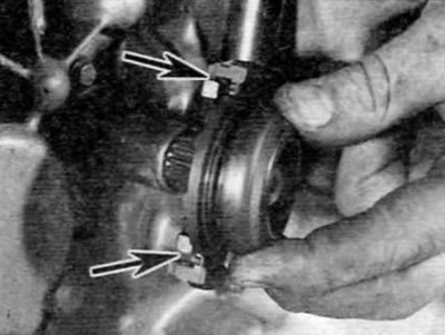
Figure 5.3. Unhook the clutch release bearing from the fork and remove it from the input shaft (mA5 and VEZ/5 gearboxes)
4. Now you should remove the clutch release lever from the top of the release fork shaft. This is done in one of two ways, depending on the type of gearbox and year of manufacture. Determine the method of attaching the release lever to the release fork shaft and, depending on the type, proceed as follows:
- a) If the release lever is secured to the shaft with a roll pin, knock out the roll pin with a suitable punch and remove the release lever from the top of the release fork shaft (figure 5.4, a, b). Purchase a new pin for installation.
- b) If the release lever is secured to the shaft by a pin with a protruding threaded end, screw the nut onto the threaded end of the pin. Tighten the nut to pull the pin out of the lever, then remove the release lever from the top of the release fork shaft. Purchase a new pin for installation.
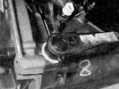
Figure 5.4, a. Knock out the cylindrical pin with a suitable center punch...
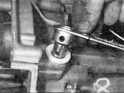
Figure 5.4, b....and remove the release lever from the top of the release fork shaft (mA5 and VEZ/5 gearboxes)
5. Press the locking tabs, then release the upper sleeve from the housing and remove it from the release fork shaft. Unhook the shaft from the lower bushing and remove it from the gearbox (figure 5.5, a, b). The lower bushing can then be removed from the gearbox housing.
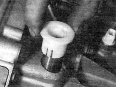
Figure 5.5, a. Release the upper bushing from the gearbox housing and remove it from the shaft...
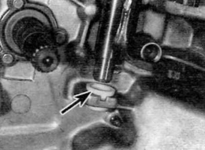
Figure 5.5, b....then release the shaft from the lower sleeve (marked with an arrow) and take it out of its normal position (mA5 and VEZ/5 gearboxes)
Gearbox BE4/5
6. Squeeze the tabs on the clamp and remove the release fork from the ball stud. Remove the adjusting shim if applicable. Unscrew the support pin from the gearbox housing (Figure 5.6, a-c).
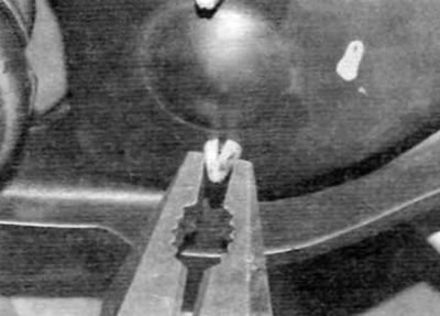
Figure 5.6, a. Squeeze the clamp and remove the disconnect plug...
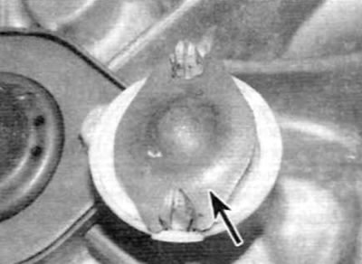
Figure 5.6, b....remove the adjusting shim (marked with an arrow)...
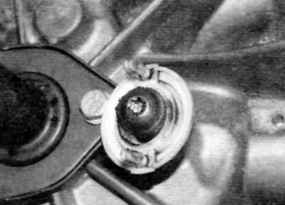
Figure 5.6, c...and then unscrew the stud with the ball end (gearbox BE4/5)
7. Slide the clutch release bearing off the input shaft guide sleeve and disengage the release fork levers (figure 5.7).
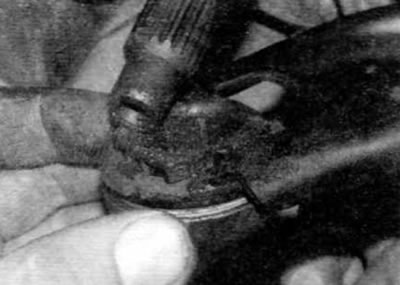
Figure 5.7. Disconnect the clutch release bearing from the release fork (gearbox BE4/5)
Inspection
8. Check the release mechanism and replace any component that is worn or damaged. Carefully inspect all bearing running surfaces and contact areas.
9. When checking the clutch release bearing directly, keep in mind that it is recommended to replace it without fail. Check that the contact side of the clutch release bearing rotates smoothly and easily, without noise or binding. Also make sure that the surface itself is smooth and not worn, and that there are no cracks, pitting or scuffs. If there is any doubt about the condition, the bearing should be replaced.
Installation
MA5 and VEZ/5 gearboxes
10. Apply a small amount of molybdenum disulfide grease to the shaft bushings and the contact surfaces of the release fork.
11. Position the lower bushing in the gearbox, ensuring it is securely fixed by the mounting tabs, and install the release fork shaft (figure 5.11). Slide the upper sleeve down the shaft and secure it in the gearbox housing.
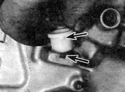
Figure 5.11. Make sure that the lower bushing protrusion is correctly positioned in the gearbox housing (mA5 and VEZ/5 gearboxes)
12. Install the release lever onto the shaft. Align the hole in the lever with the hole in the shaft and secure the shaft by inserting a new roll pin or retainer into the hole. Place the clutch release bearing onto the input shaft guide sleeve and engage it with the release fork.
13. Install the gearbox as described in Chapter 7.
Gearbox BE4/5
14. Apply a small amount of molybdenum disulfide grease to the ball stud.
15. Insert the outer end of the release fork through the rubber boot on the side of the front section of the transmission housing.
16. Engage the release fork levers with the clutch release bearing lug, and then slide the clutch release bearing onto the input shaft guide sleeve.
17. Place the adjusting shim on the ball stud clamp tabs and then place the fork on the stud, making sure the clamp tabs engage correctly with the fork (figure 5.17).
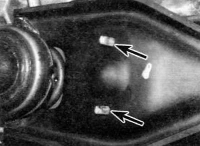
Figure 5.17. Correctly insert the locking tabs (marked with arrows) into engagement with the release fork (gearbox BE4/5)
18. Install the gearbox as described in chapter 7.