English Русский
Български
Беларускі
Український
Српски
Hrvatski
Română
Polski
Slovenský
Magyar
Bookmark Articles Sitemap Contacts
Company Hyundai Company Opel Company Skoda Company Kia Company Mitsubishi Company LADA Company Audi
PeugeotBook.ru


Series 100   Series 200   Series 300   400-500   Series 600   Crossovers   Others
 
Peugeot 405 (1987-1997) Peugeot 406 (1995-2004)

Instrument cluster (models from 1993) (Peugeot 405)

  • Main
  • 40X
  • Peugeot 405 (1987-1997)
  • Body and interior
  • Interior (internal elements)
  • Instrument cluster (models from 1993)
0
Table of contents: Removal 🠇 Installation 🠇

Removal


1. Remove the negative cable from the battery.

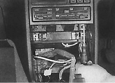
2. Remove the center console.
2. Remove the center console.


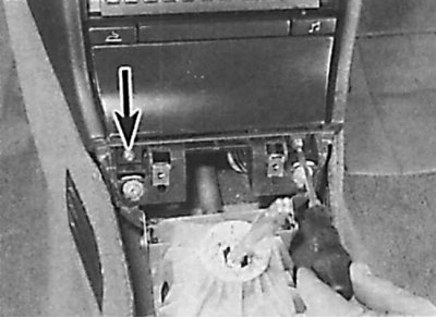
3. Unscrew two screws (indicated by an arrow), located at the bottom of the ashtray nest.

4. Remove the radio.
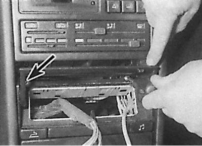
4. Remove the radio.


5. Unscrew two screws (indicated by an arrow) fastenings from the top of the radio frame.
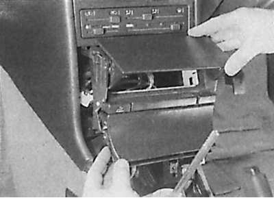
5. Unscrew two screws (indicated by an arrow) fastenings from the top of the radio frame.


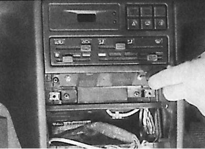
6. Remove the radio frame.


6. Remove the radio frame.


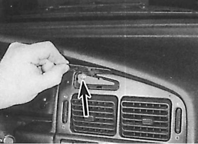
7. Using a thin screwdriver, remove the decorative plate from the upper corner of the frame of the central nozzles of the ventilation system and unscrew the exposed screw (indicated by the arrow).
7. Using a thin screwdriver, remove the decorative plate from the upper corner of the frame of the…

8. Remove the four screws securing the trim panel located underneath the HVAC control panel. Two screws are accessible from the front (drawing on the left) and two from the bottom (drawing on the right).
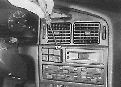


8. Remove the four screws securing the trim panel located underneath the HVAC control panel. Two…


9. Using a thin screwdriver, remove the switches located under the central nozzles of the ventilation and heating system to access the instrument panel mounting screw.
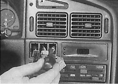
9. Using a thin screwdriver, remove the switches located under the central nozzles of the…


10. Unscrew the instrument panel mounting screw.
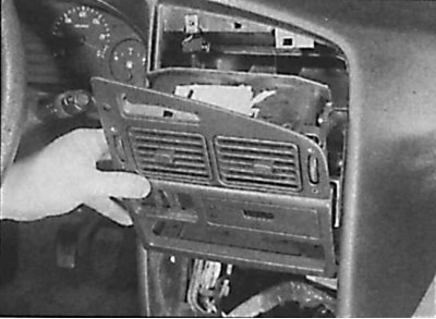
10. Unscrew the instrument panel mounting screw.


11. Pull the panel with the ventilation nozzles forward, disconnect the electrical wiring from the clock and remove the panel with the ventilation nozzles.


11. Pull the panel with the ventilation nozzles forward, disconnect the electrical wiring from the…


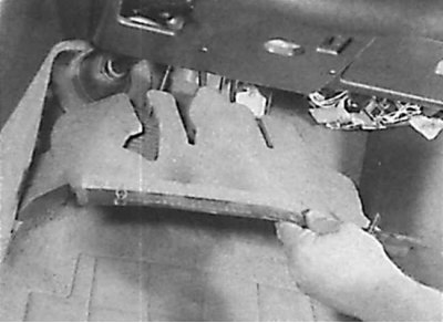
12. Release the fastening brackets and unscrew the carpet covering above the pedals.
12. Release the fastening brackets and unscrew the carpet covering above the pedals.


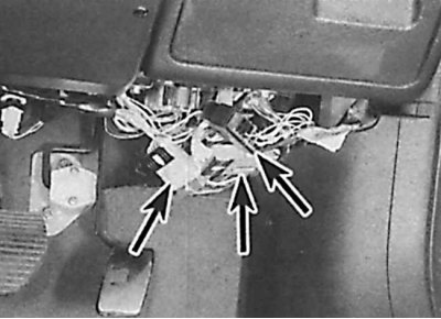
13. Disconnect three electrical connectors (indicated by arrows).
13. Disconnect three electrical connectors (indicated by arrows).


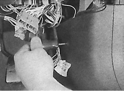
14. Remove the driver's side trim mounting screw to access the electrical connector.
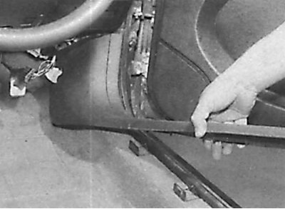
14. Remove the driver's side trim mounting screw to access the electrical connector.


15. Remove the trim panel.
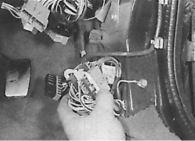


15. Remove the trim panel.


16. Release the two mounting brackets and remove the electrical connectors from the suspension. Disconnect the electrical connectors.

17. Unscrew the ground bus mounting bolt and release the wire harness from the mounting brackets under the panel.
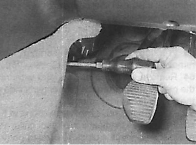
17. Unscrew the ground bus mounting bolt and release the wire harness from the mounting brackets…


18. Under the central part of the panel, unscrew the screws securing the side trim of the central part of the panel.
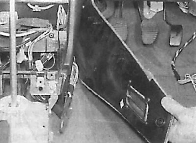
18. Under the central part of the panel, unscrew the screws securing the side trim of the central…


19. Remove the side trim of the center panel to access the heater ducts.
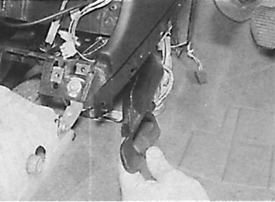


19. Remove the side trim of the center panel to access the heater ducts.


20. Unscrew the screws and remove the air ducts.

21. Remove the clamp securing the wiring harness to the suspension in the center of the driver's side dash.
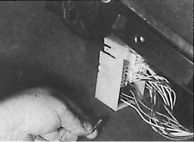
21. Remove the clamp securing the wiring harness to the suspension in the center of the driver's…


22. Release the plastic clips securing the large connector block to the driver's side center panel hanger, then disconnect the connectors from the connector block.

23. In the same way, on the passenger side, release the plastic clips securing the connector block to the floor suspension and to the heater.

24. Release the fastening brackets and remove the carpet from under the panel.

25. Loosen the mounting screw and remove the passenger side trim, release the mounting brackets and remove the wiring connector block. Disconnect the connector from the connector block.
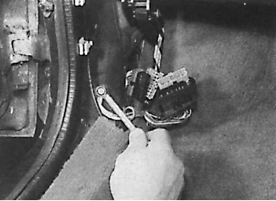


25. Loosen the mounting screw and remove the passenger side trim, release the mounting brackets and…


26. Unscrew the ground busbar mounting bolt and release the wire harness from the mounting brackets.
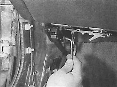
26. Unscrew the ground busbar mounting bolt and release the wire harness from the mounting brackets.


27. Unscrew the screw and remove the hood release lever.

28. Remove the steering column covers.

29. Remove the steering column.
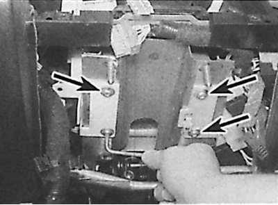
29. Remove the steering column.


30. Unscrew the screws (indicated by arrows) fasteners and remove the wiring connector hanger from the left side of the steering column.


31. Unscrew the two mounting screws and remove the wiring connector hanger from the right side of the steering column.

32. Remove the instrument cluster.

33. Disconnect the wire from the brake light switch.
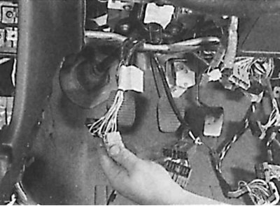
33. Disconnect the wire from the brake light switch.


34. Disconnect the main wire harness connectors from the connector block located under the driver's side dash.

35. Remove the screw securing the electrical wiring harness on the driver's side, near the clutch pedal.
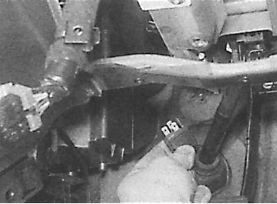
35. Remove the screw securing the electrical wiring harness on the driver's side, near the clutch…


36. Remove the relay from the connector at the rear of the steering column hanger.
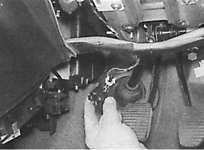
36. Remove the relay from the connector at the rear of the steering column hanger.


37. Remove the connector from the suspension.

38. Remove the heater control panel.

39. While working in the engine compartment, remove the grille located in front of the windshield.
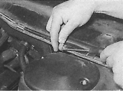
39. While working in the engine compartment, remove the grille located in front of the windshield.


40. Remove the plastic shield mounting bracket.
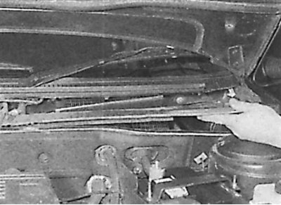
40. Remove the plastic shield mounting bracket.


41. Remove the plastic shield from the passenger side.

42. Remove the heater air intake grille and move the control unit casing to the side to access the panel mounting nuts.
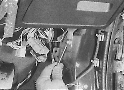
42. Remove the heater air intake grille and move the control unit casing to the side to access the…


43. Unscrew the bolts (one on each side) lower instrument panel mount.
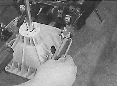
43. Unscrew the bolts (one on each side) lower instrument panel mount.


44. Unscrew the two lower instrument panel mounting bolts located on both sides of the center console.
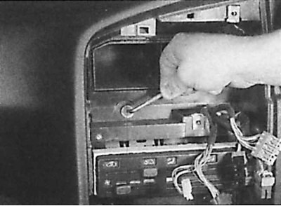
44. Unscrew the two lower instrument panel mounting bolts located on both sides of the center…


45. Unscrew the central upper panel mounting bolt located above the heater control unit.
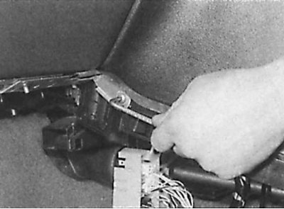
45. Unscrew the central upper panel mounting bolt located above the heater control unit.


46. Unscrew the two rear central bolts securing the panel to the heater.
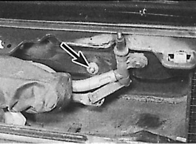
46. Unscrew the two rear central bolts securing the panel to the heater.


47. At the rear of the engine compartment, unscrew the three nuts (indicated by an arrow) instrument panel fastenings.

48. Move the panel away from the engine compartment bulkhead.
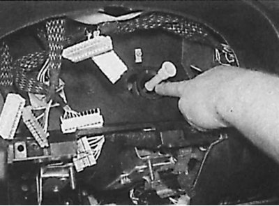
48. Move the panel away from the engine compartment bulkhead.


49. Disconnect the speedometer drive cable.

50. Remove the instrument panel from the vehicle.

Installation


To install the instrument panel, follow the steps in reverse order to the removal process.
This article is available at russian, bulgarian, belarusian, ukrainian, serbian, croatian, romanian, polish, slovak, hungarian
Article reviewed by editor: Shirokov Arseny
Share information:
Previous
Peugeot 405: Interior (internal elements)
Next

Instrument cluster (models before 1992)
Center console — removal and installation
Headlining — Removal and Installation
Interior trim — removal and installation
Rear side seat belts (combi models)
 
See similar information for other Peugeot models

➨ Fuel filter renewal — carburetor models Peugeot 106 (1991-2003)
➨ Liquid crystal display on the instrument cluster Peugeot 207 (2006-2014)
➨ Removal and installation of the instrument panel on models… Peugeot 305 (1977-1989)
➨ Instrument cluster — removal and installation Peugeot 605 (1989-2000)
➨ Instrument cluster. Indicator lights Peugeot 806 (1994-2002)
Link to this article in different formats
Comments and feedback from visitors
No comments yet


Add two numbers 17 + 22


Peugeot 406 (1995-2004) 
  • General information
  • User manual
  • Maintenance (gasoline)
  • Maintenance (diesel)
  • Power unit
  • Gasoline engines
  • Diesel engines
  • Engine overhaul
  • Cooling and heating
  • Fuel system (gasoline)
  • Fuel system (diesel)
  • Engine electrical equipment
  • Transmission
  • Clutch and drive shafts
  • Mechanical gearbox
  • Automatic gearbox
  • Chassis, running gear
  • Brake system
  • Car suspension
  • Steering
  • Body and interior
  • Exterior (external elements)
  • Interior (internal elements)
  • Doors, locks and windows
  • Electrical equipment
  • Equipment and devices
  • Electrical circuits
Peugeot 405 (1987-1997) 
  • General information
  • User manual
  • Maintenance
  • Power unit
  • Petrol engines 1.4 l
  • Petrol engines 1.6-2.0 l
  • Diesel engines
  • Ignition system
  • Fuel system (carburetor)
  • Single point fuel injection
  • Multipoint fuel injection
  • Cooling and lubrication system
  • Exhaust system
  • Transmission
  • Clutch
  • Manual gearbox MA
  • Manual gearbox BE
  • Automatic gearbox
  • Drive shafts
  • Chassis, running gear
  • Steering
  • Front suspension
  • Rear suspension
  • Brake system
  • Body and interior
  • Exterior (external elements)
  • Interior (internal elements)
  • Doors, locks and windows
  • Electrical equipment
  • Equipment and devices
  • Electrical circuits
PeugeotBook.ru © 2018–2026 | Mobile version | Sitemap: EN BG BY UA RS HR RO PL SK HU | Write message | Site search | Add to bookmarks | Peugeot owners
106 (1991-2003) | 206 (1998-2012) | 207 (2006-2014) | 305 (1977-1989) | 306 (1993-2002) | 307 (2001-2008) | 405 (1987-1997) | 406 (1995-2004) | 605 (1989-2000) | Partner-I (1996-2008) | Eurovans-807 (2002-2014) | Eurovans-806 (1994-2002) | J5 (1981-1993) |
Cookies are used to ensure the correct display of pages on the site.