
Cylinder blocks (see illustration 1.0) and cylinder heads (see illustration 1.0a) made of light metal alloy.
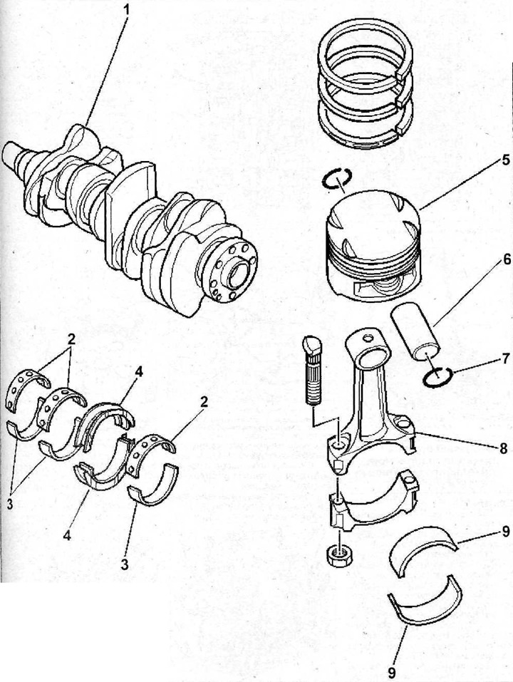
Crankshaft (see illustration 1.06) rotates in the cylinder block on four main bearings. The main bearing No. 2 is equipped with thrust half rings that regulate the axial clearance of the shaft. The connecting rods are attached to the crankshaft by means of connecting rod bearings, and to the pistons by piston rings. The pistons are made of aluminum alloy and are equipped with three piston rings - two compression and one oil scraper
Camshafts (see illustration 1.0c) rotate in the cylinder heads and are driven from the crankshaft by a toothed belt. The camshaft cams push hydraulic tappets, which in turn actuate the valves. Tappets automatically adjust valve clearances.
Lubricant is pumped into the engine by an oil pump. Oil is sucked from the sump through a mesh oil intake, then driven through the filter. It then flows to the main bearing caps and cylinder block/crankcase, from where it is distributed over the crankshaft (main bearings) and camshafts. Connecting rod bearings are supplied with oil through internal holes in the crankshaft, oil is supplied to the camshaft bearings under pressure. The camshaft cams and valves are lubricated by draining oil, as are all other engine components.
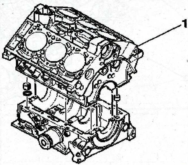
1.0 Cylinder block
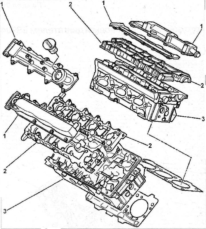
1.0a Cylinder heads
1 - cylinder head cover
2 - camshaft bearing housing
3 - cylinder block
1.0b Cylinder heads
1 - crankshaft
2 - upper shells of the main bearings of the crankshaft
3 - lower shells of the main bearings of the crankshaft
4 - persistent half rings
5 - piston
6 - piston pin
7 - retaining ring
8 - connecting rod
9 - connecting rod bearing shells
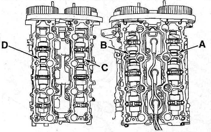
1.0v Camshafts
A - identification mark of the right exhaust camshaft
B - identification mark of the right intake camshaft
C - identification mark of the left intake camshaft
D - identification mark of the left exhaust camshaft