
24. Examine contact surfaces of pushers with cams on presence of the developed places and scratches. Check the walls of the pushers, as well as the holes for them in the cylinder head for damage and wear. If the pusher is suspected to be defective or it is visible that it is worn out, then it should be replaced with a new one.
25. Install the pushers, each in its place, after lubricating them with MOLYDAL GB SP 370G oil. Check up ease of a course of pushers in a head of the block of cylinders.
26. Remove any remaining oil from the threads of the camshaft bearing housing bolts.
27. Apply a thin layer of MOLYDAL GB SP 370G oil to the bearing journals and camshaft lobes.
28. Install the camshafts in their seats.
29. Check that the alignment pins are present 12. Apply layer E of SILICONE CATEGORIE 2 sealant (AUTOJOINT OR) along the perimeter of the bearing housings (see illustration) and install the bearing housings in their seats.
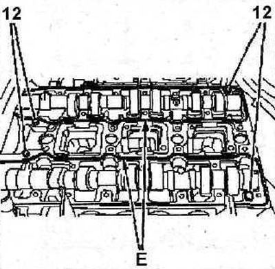
4.29 Check that the alignment pins are present 12. Apply Layer E of SILICONE CATEGORIE2 (AUTOJOINT OR) along the perimeter of the bearing housings
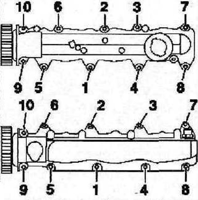
30. Tighten the bearing housing bolts in several passes in the sequence shown in the illustrations:
- 1st pass - tighten the bolts by hand;
- 2nd pass - tighten the bolts with a force of 2 Nm;
- 3rd pass - tighten the bolts to 8 Nm.
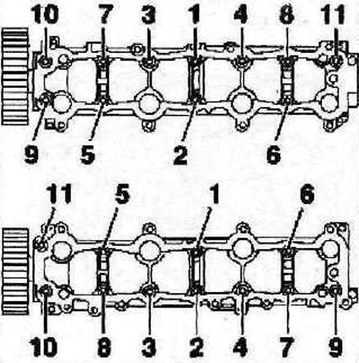
4. 30 The sequence of tightening the bolts of the camshaft bearing housings. Right cylinder head
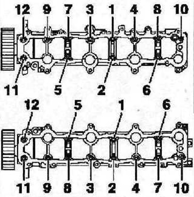
4.30a The sequence of tightening the bolts of the camshaft bearing housings. Left cylinder head
Attention! Composite cylinder head gaskets; minor damage to gaskets can be repaired by applying SILICONE CATEGORIE 2 sealant.
31. Install the cylinder head covers. Tighten their mounting bolts in the sequence shown in the illustrations. Torque:
- 1st pass tighten the bolts by hand;
- 2nd pass - tighten the bolts with a force of 5 Nm;
- 3rd pass - tighten the bolts to 10 Nm.
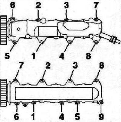
4.31 The sequence of tightening the bolts for fastening the covers of the right cylinder head
4.31a The sequence of tightening the bolts of the covers of the left cylinder head
32. Make sure that the seal seats are clean, if necessary, remove the remnants of the old sealant.
33. Lubricate the sealing lips of the new oil seals with clean engine oil. Do not lubricate the outer edge of the seal.
34. Pack new camshaft seals using a suitable drift, such as a drift «A» 0187-D (see illustration).
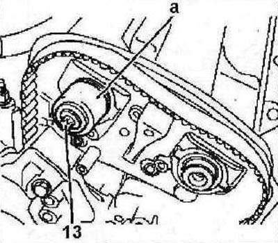
4.34 Stamp new camshaft seals using a suitable drift, e.g «a» 0187-D
35. Fix each camshaft hub with bolt 13 (see illustration 4.34).
36. Screw in the top bolts of fastening of a back cover of a drive of the gas-distributing mechanism.
37. Remove the upper right engine mount.
38. Install the camshaft gears together with the hubs 5. Flange C of the intake camshaft gear should face away from the engine, and flange C of the exhaust camshaft gear should face the engine (see illustration).
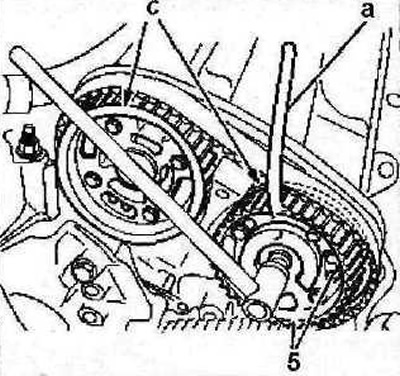
4.38 Install the camshaft gears together with the hubs 5, the flange C of the inlet camshaft gear should face away from the engine, and the flange C of the exhaust camshaft gear should face the engine
Attention! The camshaft gears are identical and interchangeable.
39. Lock the gears with a special key «A», whose catalog number is 0187-F (see illustrations 4.38 and 2.13a), and tighten the bolts of their fastening either immediately with a force of 80 Nm, or in several passes:
- 1st pass - tighten the bolts with a force of 20 Nm;
- 2nd pass - Tighten the bolts 57°.
40. Install the timing belt (see relevant chapter).
41. Further, the installation of the dismantled components is carried out in the reverse order of removal.