
2. Remove the protective cover 1 of the motor (see illustration).
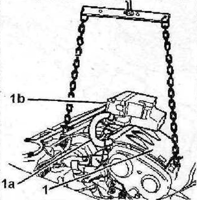
2.2 Remove the protective cover 1 of the motor
3. Disconnect the multi-pin plug 1a of the engine control unit (see illustration 2.2).
4. Move engine control unit 1b away from the work site (see illustration 2.2).
5. Install a support beam on the front end to raise the engine and relieve its mounts, or lift the engine with a crane (see illustration 2.2).
6. Disconnect the jet link 2, and then remove the right engine mount 3 (see illustration).
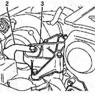
2.6 Disconnect the jet link 2 and then remove the right engine mount 3
7. Remove the accessory drive belt (see relevant chapter).
8. Remove the power steering pump pulley (see illustration).
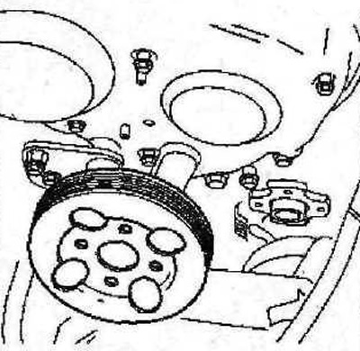
2.8 Remove the power steering pump pulley
9. Remove the protective covers 4 of the timing gear (see illustration).
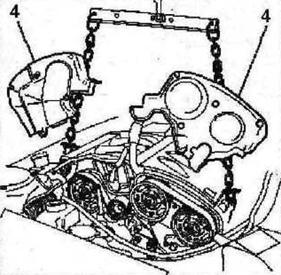
2.9 Remove the protective covers 4 of the timing gear drive
10. Remove the tensioner roller 5 of the timing belt drive (see illustration).
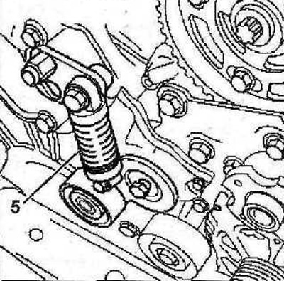
2.10 Remove the tensioner pulley 5 of the timing belt drive
11. Remove support bracket 6 (see illustration).
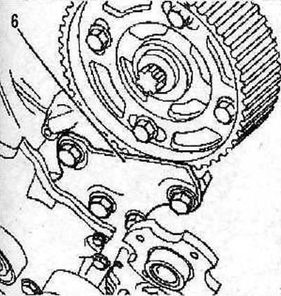
2.11 Remove support bracket 6
12. Remove the belt pulley 7 from the crankshaft, and then the protective cover 8 of the timing drive (see illustration).
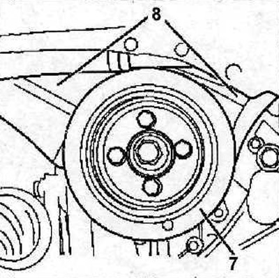
2.12 Remove the belt pulley 7 from the crankshaft, and then the protective cover 8 of the timing drive
13. Loosen the camshaft gear mounting bolts and turn the camshafts slightly in the desired direction so that the stops can be inserted «A» 0187-B into the corresponding holes with gears. blocking the shafts (see illustration 2.13). The stops should be lubricated with a little oil. Before turning the camshafts, their hubs must be locked using a special stop 0187-F (see illustration 2.13a).
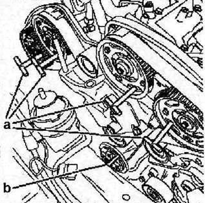
2.13 Loosen the camshaft gear mounting bolts and turn the camshaft gears slightly in the desired direction so that the stops can be inserted «A» 0187-B into the corresponding holes with gears, thereby locking the shafts
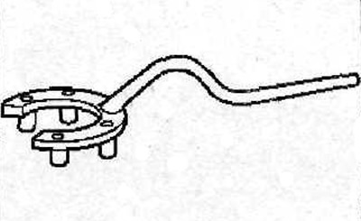
2.13a Stop 0187-F for blocking the camshaft hub
14. Stop the crankshaft by inserting the stop «b» 0187-A in the corresponding hole (see illustration 2.13)
15. Screw in the bolt 9 M8x125x75 and tighten it until the end of the bolt rests on the point «A». Bolt 11 must be tightened (see illustration).
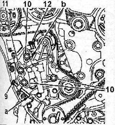
2.15 Screw in the bolt 9 M8x125x75 and tighten it until the end of the bolt rests against the point «A». Bolt 11 must be tightened
16. Loosen the bolts 10 (see illustration 2.15).
17. Screw in the bolt 12 M8x125x35 and tighten it until the end of the bolt rests on the point «b» (see illustration 2.15).
18. Unscrew bolt 9 (see illustration 2.15).
19. Remove the timing belt.
Attention! Mark with chalk, marker or paint the direction of rotation of the toothed belt if the belt is to be reinstalled. At installation it is necessary to keep the former direction of a course of a belt. Otherwise, its service life is reduced. In addition, the belt may break.