
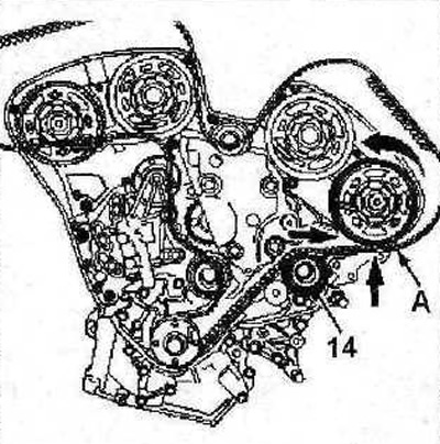
21. Check the ease of movement of the rollers 13, 14, 15, 16, as well as the gears 17 of the water pump (see illustration).
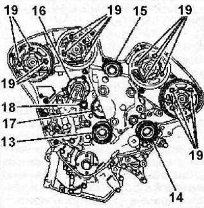
2.21 Check the ease of movement of rollers 13, 14, 15, 16, as well as gears 17 of the water pump. Tightening torque for rollers 13, 14, 15, 16 - 80 Nm, bolts 18 - 25 Nm
22. Tighten the bolts 10 with a force of 10 Nm, and then tighten them by 45° (see illustration).
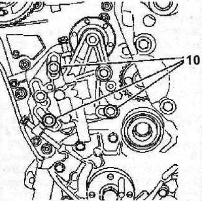
2.22 Tighten the bolts 10 to 10 Nm and then tighten them by 45°
23. Lay the toothed belt, guided by the marks and made during removal, on the crankshaft gear and secure it with the tool «A» 0187-J (see illustration).
2.23 Lay the toothed belt, guided by the marks made during removal, on the crankshaft gear and secure it with the tool «A» 01B7-J
24. Check the ease of movement of the camshaft gears by first turning them clockwise so that the gear mounting bolts are in the center of the elongated holes, and do not rest against their ends (see arrows in illustration). Tighten the bolts 19 for fastening the gears with a force of 5 Nm, and then tighten them by 45°.
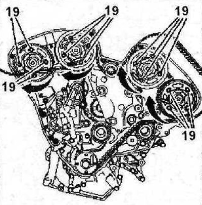
2.24 Check the ease of movement of the camshaft gears by first turning them clockwise so that the gear mounting bolts are in the center of the elongated holes, and do not rest against their ends (see arrows). Tighten the bolts 19 of the gears with a force of 5 Nm, and then tighten them by 45°
25. Lay the toothed belt on the guide roller 14 (see illustration).
2.25 Lay the toothed belt on the guide roller 14
26. If necessary, turn the camshaft gear against the direction of engine rotation to align the teeth of the belt with the grooves of the gear (see arrows in illustration 2.25).
27. Make sure that the length of the belt A between the roller 14 and the camshaft gear is properly tensioned (see illustration 2.25).
28. Lay a gear belt on a gear wheel of a camshaft of final valves of the left block of cylinders.
Attention. The offset of the belt tooth in the corresponding gear recess should not exceed the width of one tooth.
29. Lay the toothed belt on the camshaft gear of the inlet valves of the left cylinder block, roller 15 (see illustration).
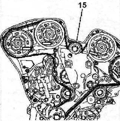
2.29 Lay the toothed belt on the camshaft gear of the inlet valves of the left cylinder block, roller 15
30. Lay a gear belt on gear wheels of camshafts of inlet and final valves of the right block of cylinders.
31. Lay the toothed belt on roller 16, gear 17 of the water pump and roller 13 (see illustration 2.31).
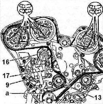
2.31 Place the toothed belt on roller 16, water pump gear 17 and roller 13
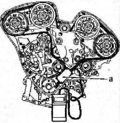
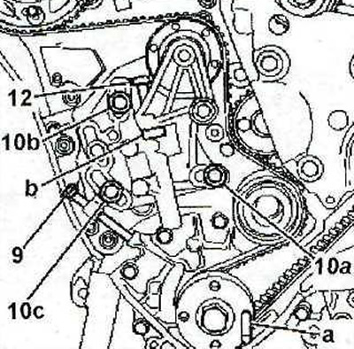
32. Screw in bolt 9 again (see illustration 2.31), to ensure proper belt tension. Make sure the camshaft gear bolts are in the center of the elongated holes, and do not rest against their ends. If the bolts are not centered, the toothed belt installation procedure must be repeated.
33. Remove fixture «A» 0187-J (see illustration 2.31).
34. Measure the tension of the toothed belt, for which fix the sensor «A» SEEM C. TRONIC 105.5 instrument for measuring the tension between the gears of the camshafts and crankshafts (see illustration). The toothed belt must be tensioned.
2.34 Measure toothed belt tension
35. Tighten bolt 9 so that the toothed belt tension is 83±2 SEEM units (see illustration).
2.35 Tighten bolt 9 so that the toothed belt tension is 83±2 SEEM units
36. Tighten the bolts 10 with a force of 10 Nm in the following sequence: first 10a, then 10b and 10c (see illustration).
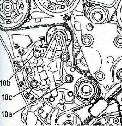
2.36 Tighten bolts 10 to 10 Nm in the following sequence: first 10a, then 10b and 10c
37. Tighten the bolts 19 for fastening the gears of the camshafts with a force of 10 Nm in the following sequence, first the bolts 19 for fastening gear 20, then gears 20a, then gears 20b and gears 20c (see illustration).
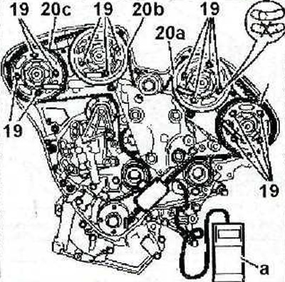
2.37 Tighten the bolts 19 for fastening the camshaft gears with a force of 10 Nm in the following sequence: first the bolts of the Reinforcing gear 20, then gear 20a, then gear 20b and gear 20c
38. Remove the device «A» for measuring belt tension (see illustration 2.37), remove the stops that were used to block the camshafts and crankshafts.
39. Rotate the crankshaft two turns in the direction of engine rotation.
Attention! Do not turn the crankshaft against the direction of engine rotation.
40. Lock the crankshaft by inserting a suitable stop «A» into the appropriate hole (see illustration).
2.40 Lock the crankshaft by inserting a suitable stop «A» into the appropriate hole
41. Loosen bolts 10a, 10b and 10c by 45°, unscrew bolt 12 (see illustration 2.40).
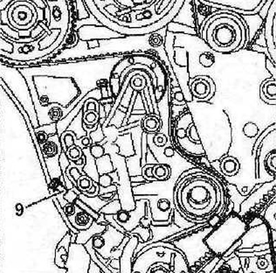
42. Loosen or tighten bolt 9 so that the template «b», whose catalog number is 0187-EZ. to adjust the dynamic tensioner had no play (see illustration 2.40).
43. Wait about 1 minute if the ambient temperature is above 15°C, otherwise, the waiting time will be longer, and check again that the pattern «b» has no play, then remove the template.
44. Tighten the bolts 10 with a force of 25 Nm in the following sequence: first 10a, then 10b and 10c (see illustration 2.40).
45. Unscrew the bolt 9, remove the stop «A «, which was used to lock the crankshaft (see illustration 2.40).
46. Again turn the crankshaft two turns in the direction of rotation of the engine, and then lock it again using a suitable stop.
47. Stop the gears of camshafts A and B using suitable stops «A» (see illustration). If the stops cannot be freely installed in the corresponding holes, then loosen the bolts 19 for fastening the gears by 45°, and then insert the stops into the holes.
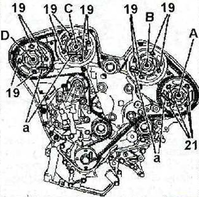
2.47 Lock the gears of camshafts A and B using suitable stops «A»
48. Similarly lock the gears of camshafts C and D (see illustration 2.47).
49. Tighten the bolts 19 for fastening the gears of the camshafts with a force of 10 Nm in the following sequence: first the bolts 19 for fastening gear 20, then gears 20a, then gears 20b and gears 20c (see illustration).
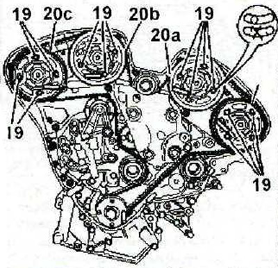
2.49 Tighten the bolts 19 for fastening the camshaft gears with a force of 10 Nm in the following sequence: first the bolts 19 for sprinkling gear 20, then gear 20a, then gear 20b and gear 20c
50. Remove the stops that were used to block the camshafts and crankshafts.
51. Further, the installation of the dismantled components is carried out in the reverse order of removal, taking into account the following:
52. The tightening torque of the belt pulley nut on the crankshaft is 25 Nm.
53. Install bracket 6, then tensioner 4 (see illustration).
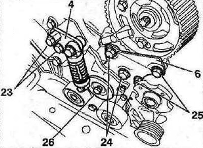
2.53 Install bracket 6, then tensioner 4
54. Screw in bolts 23, tighten bolts 24 to 39 Nm, bolts 25 to 25 Nm, and bolts 26 to 60 Nm (see illustration 2.53).
55. Establish protective covers of a drive of the gas-distributing mechanism.
56. Install the power steering pump pulley, tighten its fastening bolts with a force of 10 Nm
57. Install the accessory drive belt (see relevant chapter).
58. Install the right support 3 of the engine mount, tighten the bolts 27 and nuts 28 and 29 of its fastening with a force of 45 Nm (see illustration).
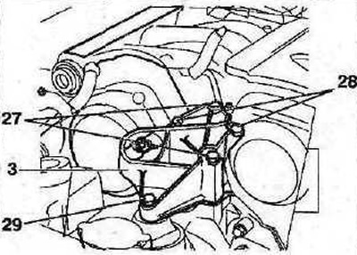
2.58 Install the right support 3 of the engine mount, tighten the bolts 27 and nuts 28 and 29 of its fastening with a force of 45 Nm
59. Connect reactive thrust 2, tighten bolts 31 to 50 Nm (see illustration).
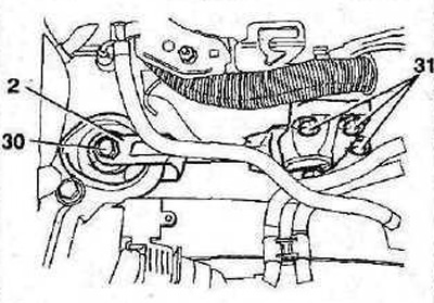
2.59 Connect torque arm 2, tighten bolts 31 to 50 Nm