
2. Remove the front wheels and fender liner.
3. Drain the coolant.
4. Drain engine oil (if necessary).
5. Remove drive shafts (see relevant chapter).
6. Remove the battery and its tray.
7. Move the slave cylinder 1 of the clutch away from the place of work (see arrows in illustration).
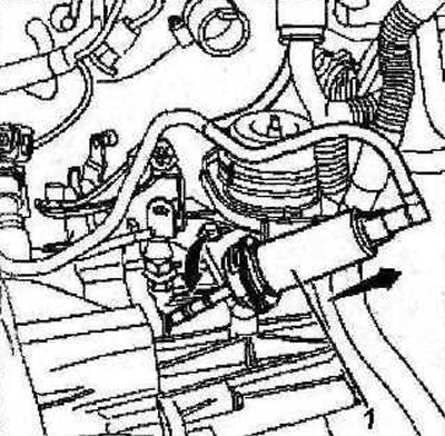
7.7 Move the slave cylinder 1 of the clutch away from the place of work (see arrows)
8. Put on a protective cover «A», catalog number of which is 0216-E2, on the slave cylinder 1 of the clutch (see arrows in illustration).
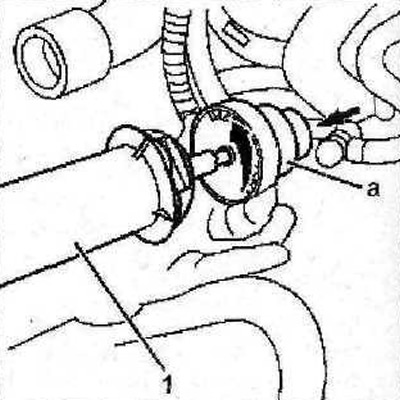
7.8 Put on the protective cover «A», catalog number of which is 0216-F2, on the slave cylinder 1 of the clutch (see arrows)
9. Move the fuse block 2 away from the place of work, disconnect wires 3, plug 4 (see illustration).
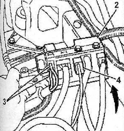
7.9 Move the fuse block 2 away from the place of work, disconnect wires 3, plug 4
10. Disconnect the supply 5 and discharge 6 coolant hoses, move pipelines 7 aside (see illustration).
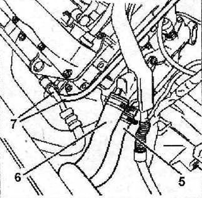
7.10 Disconnect the supply 5 and discharge 6 coolant hoses, move pipelines 7 aside
11. Disconnect and slide into) away from the work site accelerator cable 8 (see illustration).
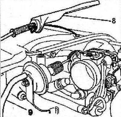
7.11 Disconnect and move away from the place of work the cable 8 of the accelerator
12. Disconnect and move pipeline 9 away from the work site (see illustration 7.11).
13. Remove the clips 10 and using a 10mm puller 0216-C1, disconnect the tip of the cable pull from the spherical head 11, and using a 13mm puller 0216-G2 from the spherical head 1 2 selector and shift rods (see illustration).
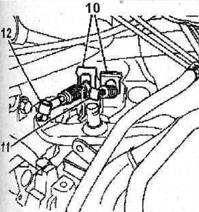
7.13 Remove the clamps 10 and using a 10 mm puller 0216-G1 disconnect the tip of the cable pull from the spherical head 11, and using a 13 mm puller 0216-G2 from the spherical head 12 of the selection and gear shift rods
14. Disconnect and move aside the low pressure hose 13 of the vacuum brake booster, heater hoses 14, pipeline 15 (see illustration).
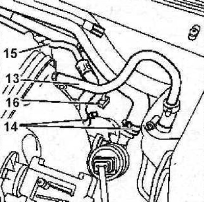
7.14 Disconnect and move aside low pressure hose 13 of the vacuum brake booster, heater hoses 14, pipeline 15
15. Disconnect the plug 16 of the sender (see illustration 7.14).
16. Move the hose 17 away from the place of work (see illustration).
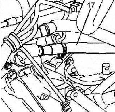
7.16 Move the hose 17 away from the place of work
17. Remove the cover 18 of the engine control unit (see illustration).
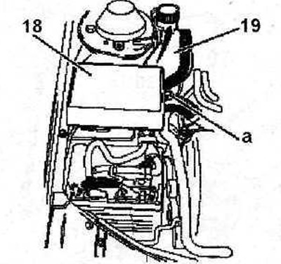
7.17 Remove cover 18 of the engine control unit
18. Pinch the low pressure hose of the power steering pump with a suitable clamp, such as a clamp «A», whose catalog number is 1512 (see illustration 7.18), disconnect the hose and move it away from the work area (see illustration 7.17).
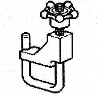
7.18 Clamp 1512
19. Move the reservoir 19 of the power steering away from the place of work, having previously plugged its openings (see illustration 7.17).
20. Disconnect plugs 20 from the engine control unit (see illustration).
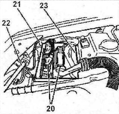
7.20 Disconnect plugs 20 from the engine control unit
21. Disconnect wire 21 «masses» (-) (see illustration 7.20).
22. Disconnect the pipeline 22, and then remove the engine control unit 23 (see illustration 7.20).
23. Feed the front cross member forward without disconnecting anything from it (see arrows in illustration).
7.23 Move the front cross member forward frequently without disconnecting anything from it (see arrows)
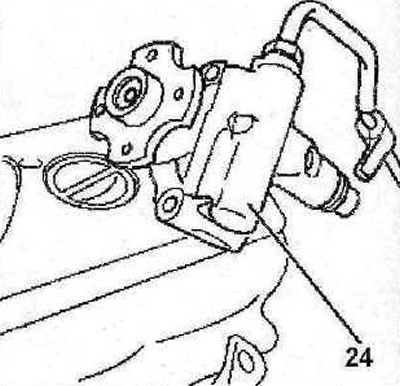
24. Remove the accessory drive belt (see relevant chapter).
25. Remove the power steering pump pulley.
26. Remove the radiator.
27. Release from the holders and move away from the place of work the pump 24 of the power steering (see illustration).
7.27 Release from the holders and move away from the place of work the pump 24 of the power steering
28. Disconnect the plug of the power wire from the air conditioning compressor.
Attention! All work related to the air conditioner should be entrusted to a specialized workshop. Do not open the refrigerant circuit yourself - risk of frostbite!
29. Release the hoses from the mounts, then move the air conditioner compressor 25 together with the bracket away from the place of work, without disconnecting the hoses from the compressor (see illustration).
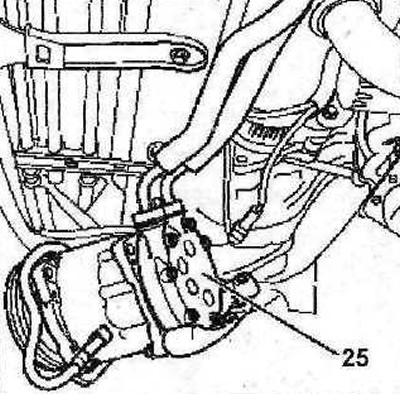
7.29 Move away from the place of work the compressor 25 of the air conditioner together with the bracket, without disconnecting the hoses from the compressor
30. Remove the belt pulley 26 from the crankshaft, move the coolant hose 27 to the side (see illustration).
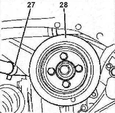
7.30 Remove the belt pulley 26 from the crankshaft, move aside the coolant hose 27
31. Disconnect the jet link 28 (see illustration).
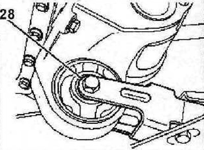
7.31 Disconnect the torque arm 28
32. Disconnect a reception pipe.
33. Remove the protective cover 29 of the engine, disconnect the plug 30 (see illustration).
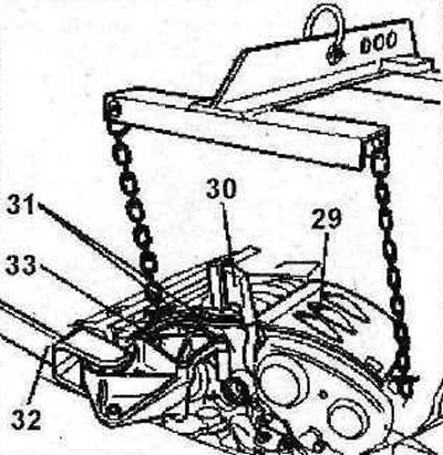
7.33 Remove the protective cover 29 of the motor, disconnect the plug 30
34. Depressurize the fuel system: workshops use a special vacuum pump for this (see illustration 7.34). Then disconnect the fuel lines 31 (see illustration 7.33).
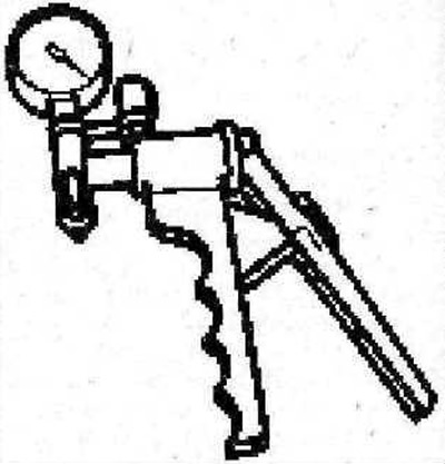
7.34 Vacuum pump, which is used to relieve pressure in the fuel system
35. Install a support beam on the front end to raise the engine and unload the power block supports, or lift the engine with a crane or hoist (see illustration 7.33).
36. Disconnect jet link 32 (see illustration 7.33).
37. Remove the right support 33 engine mounts (see illustration 7.33).
38. Remove the support 34, unscrew the bolts 35 and remove the support mounting bracket 36 (see illustration).
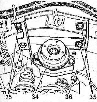
7.38 Remove support 34, unscrew bolts 35 and remove support bracket 36
39. Remove tip 37 speedometer shaft drive (see illustration).
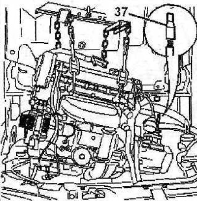
7.39 Remove tip 37 of speedometer shaft drive
40. Carefully remove the engine from the engine compartment.