



2. Cars with cruise control. Remove valve 1 together with the holder (see illustration).
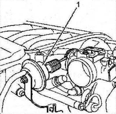
6.2 Remove valve 1 together with the holder. Vehicles with cruise control
3. Disconnect the 2 engine wire harness together with the holder (see illustration).
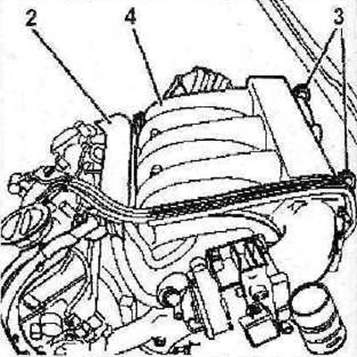
6.3 Disconnect the 2 engine wire harness together with the holder
4. Remove the lifting eyes 3 (see illustration 6.3).
5. Remove the upper part of the 4 intake manifold (see illustration 6.3).
6. Disconnect the crankcase ventilation hoses 5 (see illustration).
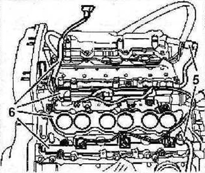
6.6 Disconnect the crankcase ventilation hoses 5
7. Remove the additional wiring harness 6 (see illustration 6.6), as well as the lower part of the intake manifold and fuel rails.
[Source of the article is posted at: www.PeugeotBook.ru]
8. Plug all openings with suitable plugs to prevent clogging of the system. All seals must be replaced.
9. Remove the timing belt of the gas distribution mechanism drive (see the relevant chapter).
10. Disconnect the supply and return hoses 7 from the thermostat housing (see illustration).
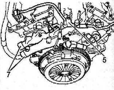
6.10 Disconnect the supply and return hoses 7 from the thermostat housing
11. Disconnect the crankcase ventilation hoses 5 (see illustration 6.10).
12. Remove the guide tube 8 of the measuring probe (see illustration).
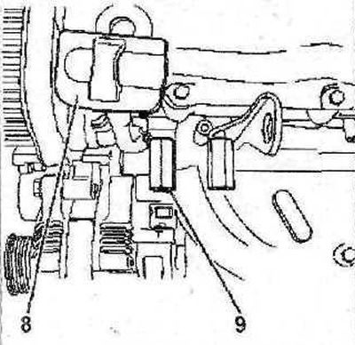
6.12 Remove the guide tube 8 of the measuring probe
13. Remove the holder 9 (see illustration 6.12). The tightening torque of the holder is 25 Nm.
14. Unscrew bolt 10, then remove bracket 11 for fastening the power steering pump (see illustration).
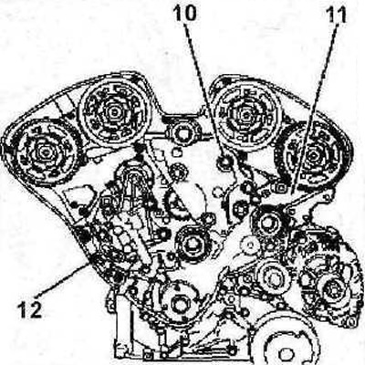
6.14 Unscrew bolt 10, then remove bracket 11 for fastening the power steering pump
15. Unscrew the M8 bolt 12 (see illustration 6.14).
16. Remove the cylinder head covers.
17. Loosen the cylinder head bolts in a spiral pattern, starting with the outer bolt (see arrows in the illustration). Unscrew the bolts in the same sequence.
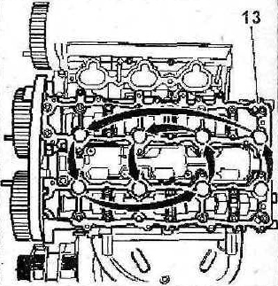
6.17 Loosen the cylinder head mounting bolts in a spiral pattern, starting with the outer bolt (see arrows)
18. Remove the head of the 13 cylinder block (see illustration 6.17).
19. Loosen the cylinder head bolts in a spiral motion, starting with the outer bolt (see arrows in the illustration). Unscrew the bolts in the same sequence and remove the cylinder head 14.
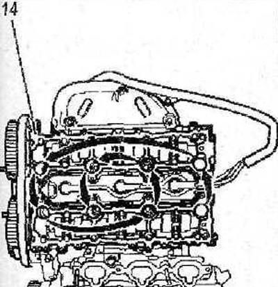
6.19 Loosen the cylinder head mounting bolts in a spiral pattern, starting with the outer bolt (see arrows). Unscrew the bolts in the same sequence and remove the cylinder head 14
20. Remove the cylinder head gaskets 15 (see illustration).
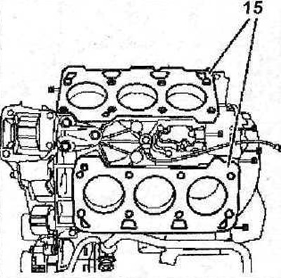
Fig. 6.20. Remove the cylinder head gaskets 15