



22. Clean holes 16 for cylinder head mounting bolts (see illustration).
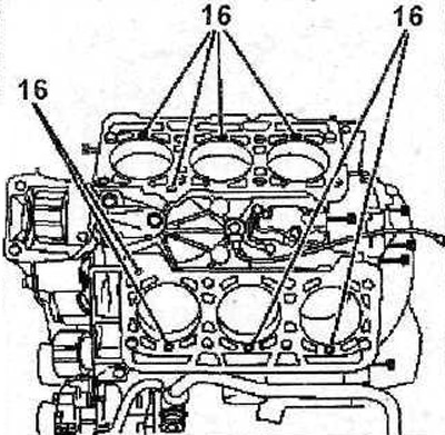
6.22 Clean holes 16 for cylinder head mounting bolts
Caution! There should be no oil or coolant in the holes for the cylinder head mounting bolts. If necessary, remove oil or coolant from the holes using a screwdriver wrapped in a rag. If oil remains in the holes, the cylinder block may be damaged when tightening the bolts.
23. Check the cylinder head for deformation and warping using a standard steel ruler. Install the ruler along the measurement lines (see illustration). Curvatures within 0.05 mm are allowed.
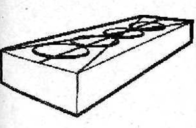
6.23 Check the cylinder head for deformation and warping using a standard steel ruler. Install the ruler along the measurement lines
24. Measure the length of the cylinder head mounting bolts. The length X of the bolt should not exceed 149.5 mm (see illustration)
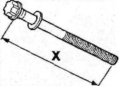
6.24 Measure the length of the cylinder head mounting bolts. The length X of the bolt should not exceed 149.5 mm
25. Clean the threads of the cylinder head mounting bolts and renew the threads if necessary.
26. Make sure that the mounting pins 17 are present, the holes 17a must be clean and dry (see illustration).
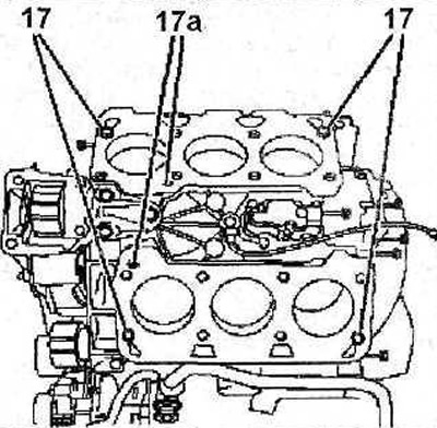
6.26 Make sure that the mounting pins 17 are present, the holes 17a must be clean and dry
27. Place new gaskets on the cylinder heads; the gaskets must be positioned so that no opening is blocked.
28. Install the cylinder heads.
29. Install the timing belt of the gas distribution mechanism drive (see the relevant chapter).
30. Apply a thin layer of MOLYKOTEG RAPIDPLUS grease to the threads and the underside of the cylinder head bolt head (see arrows in the illustration).
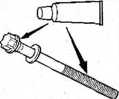
6.30 Apply a thin layer of MOLYKOTE G RAPID PLUS grease to the threads and the underside of the cylinder head bolt head (see arrows)
31. Tighten the cylinder head bolts in several passes in the sequence shown in the illustration:
- 1st pass - tighten the bolts to 20 Nm;
- 2nd pass - completely loosen the bolts;
- 3rd pass - tighten the bolts to 15 Nm;
- 4th pass – tighten the bolts by 225°.
Caution! Cylinder head cover gaskets are composite: minor damage to the gaskets can be repaired by applying SILICONE CATEGORIE 2 sealant.
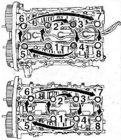
6.31 Cylinder head bolt tightening sequence
32. Install the cylinder head covers, tighten their mounting bolts in several passes in the sequence shown in Illustrations 6.32 and 6.32a:
- 1st pass - tighten the bolts by hand;
- 2nd pass - tighten the bolts to 5 Nm;
- 3rd pass - tighten the bolts to 10 Nm.
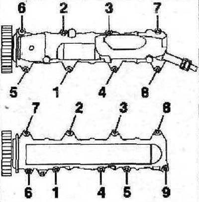
6.32 Sequence of tightening the bolts for fastening the right cylinder head cover
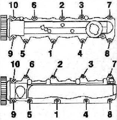
6.32a Sequence of tightening the bolts securing the left cylinder head cover
33. Screw in the M8 bolt 12, then install the bracket 11 of the power steering pump and tighten the bolts 18 of its fastening with a force of 39 Nm (see illustration).
Source available on the website peugeotbook
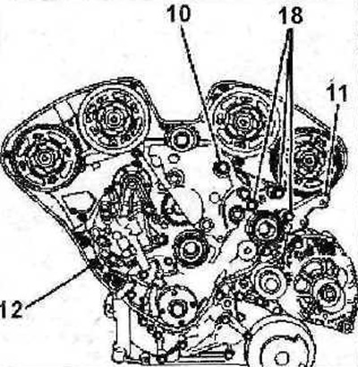
6.33 Screw in bolt M812, then install bracket 11 of the power steering pump and tighten bolts 18 of its fastening with a force of 39 Nm
34. Screw in bolt 10 and tighten it to 60 Nm (see illustration 6.33).
35. Install the dipstick guide tube.
36. Connect crankcase ventilation hoses 5, supply and return hoses 7 to the thermostat housing. Tighten bolts 19 and 21 with a force of 8 Nm, bolts 20 with a force of 25 Nm (see illustration).
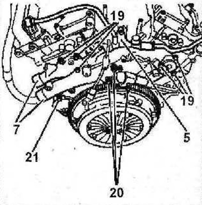
6.36 Connect crankcase ventilation hoses 5, supply and return hoses 7 to the thermostat housing. Tighten bolts 19 and 21 with a force of 8 Nm, bolts 20 with a force of 25 Nm
37. Next, the installation of the dismantled components is carried out in the reverse order of removal.