



Figure 360 shows a diagram of the cooling system, which shows the location of the individual elements of the cooling system.
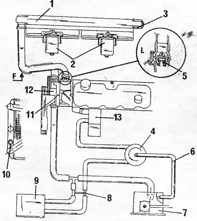
Figure 360. Cooling system diagram. 1. Radiator; 2. Electric fan; 3. Air removal point; 4. Receiver; 5. Thermostat; 6. Expansion tank pipeline; 7. Expansion tank; 8. Connector; 9. Heater; 10. Temperature switch; 11. Air release valve; 12. Water pump; 13. Oil radiator
However, some differences should be pointed out.
The water pump, driven by the crankshaft belt pulley, supplies coolant through all hoses and channels. This means that removing and installing the water pump is not difficult.
The thermostat begins to open at 86°C and is fully open at 98°C.
The radiator has two electric fans, which turn on sequentially as the temperature rises and also turn off sequentially as the temperature drops.
The cooling system has two air release valves. One is located on the radiator and the other is on the top of the engine.