
Note. All nuts disturbed during removal must be replaced without fail. This is due to the fact that the threads of these nuts are coated with a compound to lock the threaded connections (designed for one puff only). These nuts include the tie rod pivot nuts, the steering gear bolt nuts, and the countershaft pinch bolt nut.
Removing
1. Fully apply the parking brake. Raise the front of the vehicle and securely jack stands under it (see «Lifting and placing the car on supports»). Remove both front wheels.
2. Turn away nuts of fastening of spherical joints of steering rods to rotary fists and by means of a universal puller of spherical joints release pins of spherical joints (pic. 20.2).
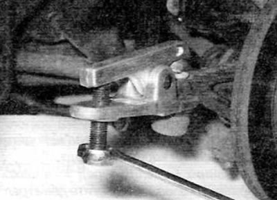
Pic. 20.2. Removing the tie rod ball joint using a ball joint puller
3. Remove the nut on the pinch bolt securing the intermediate shaft to the steering gear, and then carefully knock out the pinch bolt from the cardan joint. Discard the pinch bolt and nut; when installing, use new ones. Remove the metal clip securing the intermediate shaft to the gear.
4. Mark the relative position of the universal joint and the steering gear, and then press the universal joint up to separate it from the gear.
5. Turn out a bolt of fastening of a coupler of a back support of the engine/transmission to a support on a back part of the block of cylinders.
6. Release the clutch cable from the brackets on the subframe.
7. On models with power steering, remove the bolt (-s) pipeline fastenings (-ov) power steering to support bracket (-am) on the engine/gearbox and subframe.
8. Accurately measure and record the transverse and horizontal position of the subframe in relation to the chassis and underbody elements. In practice, there should be marks near the bolts on the subframe, and these can be used to set the installation position fairly accurately.
9. Place a jack with a suitable block of wood on the head under the subframe to perform a controlled lowering of the subframe.
10. Remove the four rear bolts and two front subframe mounting bolts, and then gently lower the subframe slightly.
11. On models with power steering, place a suitable container under the steering gear. On early models, mark the piping nipple connections for proper installation position, then remove the supply and return piping flare nuts from the steering box. On later models, remove the bolt securing the hydraulic fluid line flange plate to the steering gear case and disconnect the flange plate from the steering gear. On all models, allow the power steering fluid to drain into a container. After draining the fluid, properly plug the ends of the lines and ports in the steering box to prevent dirt from entering. Be aware that later models will require new o-rings for the pipe ends for installation.
12. Remove two screws (if applicable), then release the heat shield and remove it from the top of the steering assembly.
13. Turn out two bolts of fastening of the steering mechanism and take remote elements from apertures of a stretcher (pic. 20.13).
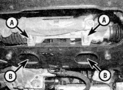
Pic. 20.13. Turn out bolts of fastening of the steering mechanism (A) and remove the spacers (IN) from holes in the frame
14. Remove the steering mechanism from under the right wheel arch (right hand drive models) or from under the left wheel arch (left hand drive models).
Repair
15. Inspect the steering gear for signs of wear or damage and make sure the rack moves freely over its full travel with no signs of binding or excessive play between the steering gear and rack. It is possible to repair the steering gear housing assembly, but this work should be done by a Peugeot/Citroen dealer. The only elements that an amateur mechanic can replace are tie rod ball joints (see paragraph 23).
16. Inspect all steering gear fittings for signs of leakage and make sure all union nuts are securely tightened. Also inspect the steering cylinder for signs of leakage or damage and replace if necessary.
Installation
17. Keep in mind that all nuts disturbed during removal must be replaced without fail. This is due to the fact that the threads of these nuts are coated with a compound to lock the threaded connections (designed for one puff only). These nuts include tie rod pivot nuts and steering gear bolt nuts.
18. Bring the steering gear assembly to its original position through the right or left side of the vehicle (whichever is applicable).
19. Install the spacers in the subframe holes, and then screw in the appropriate bolts. Tighten the bolts to the specified torque.
20. Fix the heat shield to the top of the steering gear and tighten the two corresponding screws securely (if applicable).
21. On power steering models, wipe clean the power steering lines and ports in the steering box. On early models, connect the supply and return lines to the appropriate ports on the steering box. Tighten the union nuts securely. On later models, install new o-rings on the ends of the pipes. Position the hydraulic fluid line flange plate on the steering gear housing and secure with the bolt.
22. Raise the jack and place the subframe in its original position. Correctly position the subframe, focusing on the dimensions made during removal, or on the marks made near the bolts. Screw in the front and rear subframe mounting bolts and tighten them to the specified torque.
23. If applicable, install the power steering fluid line to the support bracket (-s) on the engine/gearbox and subframe.
24. Attach the clutch cable to the brackets on the subframe.
25. Screw in the bolt securing the tie rod of the rear engine / gearbox mount to the cylinder block and tighten to the prescribed torque (refer to relevant part chapter 2).
26. Fix the cardan joint of the intermediate shaft in the splined hole of the steering gear (align the marks made before removal). Properly install the metal clip on the universal joint between the intermediate shaft and the steering gear, and then install a new tie bolt and nut, making sure that the tabs on the bolt fit into the cutouts in the universal joint. Tighten the nut to the specified torque.
27. Insert the ball joints of the steering rods into the steering knuckles, and then screw on each new nut. Tighten nuts to specified torque.
28. Check one last time that all cables, lines and hoses are routed correctly and securely fixed with all necessary clamps.
29. Install the wheels, then lower the vehicle and tighten the wheel bolts to the specified torque.
30. Fill the booster reservoir and bleed the air from the hydraulic actuator as described in paragraph 21.
31. Finally, check the front wheel alignment and adjust if necessary (see paragraph 24).