
 |  |
2. To remove the steering mechanism, loosen the nuts of the front wheels and jack up and support the front of the machine. Remove wheels.
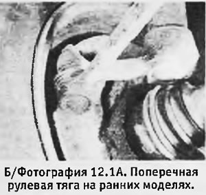
3. Disconnect the ball joints at the ends of the tie rods. On early models, use a ball joint remover; on late models, loosen the locknuts on the outer ends of the links and unscrew the links from the bearings.
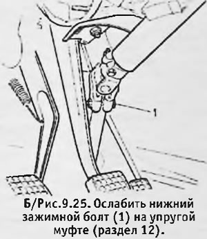
4. Working in the salon, loosen the one under "torpedo" clamping bolt on the lower end of the steering column flexible coupling.
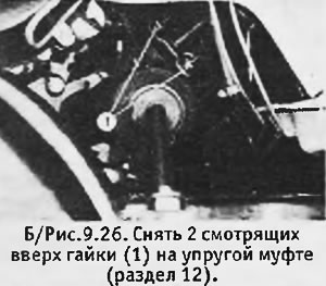
5. Turn out 2 nuts looking upwards on an elastic coupling and to disconnect a steering column from the coupling.
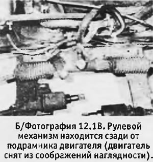
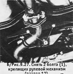
6. Working under the machine, unscrew and remove the 2 bolts securing the steering box to the body.
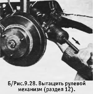
7. Carefully remove the steering gear.
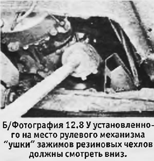
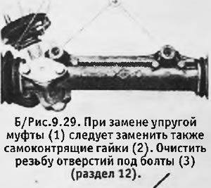
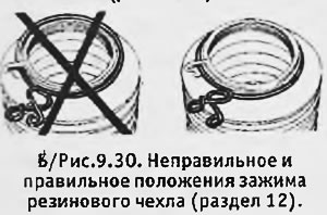
8. Repair or overhaul of the steering mechanism must be carried out by a specialist with the necessary equipment. Check the condition of the flexible coupling and, if in doubt, replace it. When replacing the coupling, it is necessary to install new self-locking nuts and tighten them to the required torque. Replace rubber boots in the same way if they are worn or damaged. If there are cracks on the covers through which grease flows, it is necessary to contact a specialist to check the internal hinges, which could get dirt and dust. When replacing boots, check that the wire clips are installed correctly (see b/fig. 9.30), and place "ears" clips so that after installing the steering gear they look down (see photo). Clean the mounting bolts and the threads of the bolt holes.
 |  |
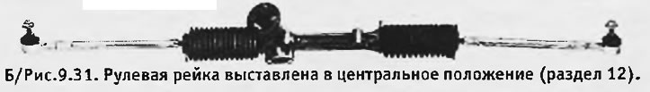
9. Before installing the steering mechanism in place, check that the steering wheel is exactly in the center and center the gear rack (see b/fig. 9.31).
10. Install the steering gear in place. Lubricate the threads of the 2 mounting bolts with thread locking compound and install new washers. Insert the bolts and tighten them to the correct torque.
11. Connect the lower end of the steering column to the elastic coupling, install 2 new self-locking nuts and tighten them to the desired torque.
12. Install the steering column lock. Move the steering wheel up and down until it stops and set it to the middle position. Tighten the clamping bolt at the bottom of the flexible coupling to the correct torque.
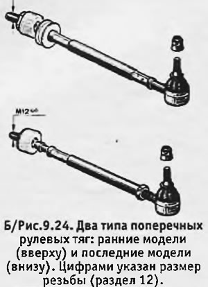
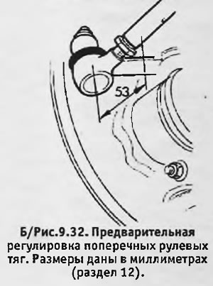
13. Connect the outer ends of the tie rods to the pivot pin arms. On early models, install the ball joint pins into the arms and secure them with new self-locking nuts, tightening them to the desired torque. On the latest models, screw the transverse rods into the ball bearings as shown in B / fig. 9.32 (the distance shown in the figure should be 53 mm).
14. Reinstall the front wheels, lower the machine to the ground and tighten the wheel nuts to the correct torque.
15. Adjust the toe of the front wheels (see next section).