
Removing
Note. When installing the sensor, a new sealing washer must be used.
1. The thermostatic sensor is located on the side of the thermostat/fuel filter housing.
2. For easier access to the sensor, remove the appropriate intake air lines as described in paragraph 3.
3. Drain the coolant from the cooling system as described in chapter 1B.
4. Loosen the clamping screw or nut (whichever is applicable) and disconnect the high idle cable end from the cable on the fuel injection pump high idle lever (pic. 10.4).
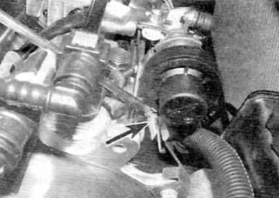
Pic. 10.4. Loosen the screw (arrowed), and then remove the lug from the high idle cable (models with 1.9 l engine)
5. Remove the cable from the adjusting screw located in the bracket on the high pressure fuel pump.
6. Using a suitable open end wrench, unscrew the thermostatic sensor from the thermostat/fuel filter housing and remove the sensor along with the cable. Remove the sealing washer and discard it; when installing, use a new one.
Installation
7. Install the sensor using a new sealing washer and tighten securely.
8. Route the cable correctly and then thread it through the adjusting screw on the bracket.
9. Pass the cable through the high idle lever and install the lug on the cable, but do not tighten the clamp screw or nut (whichever is applicable).
10. Adjust the cable as described in the following paragraphs.
Adjustment
11. If you have not already done so, release the clips on the right side and on the top plane of the engine cover, and then carefully, so as not to lose the rubber mounts, remove the cover (pic. 3.1, a-c).
12. With the engine cold, loosen the high idle cable end clamp screw/nut all the way towards the flywheel end of the engine, and then remove any slack in the cable. Pregnant. when the high idle lever touches the appropriate limiter, and the end of the cable is firmly pressed against the lever, tighten the clamp screw or nut.
13. Make sure that the high idle lever is pressed firmly against the appropriate limiter. If necessary, adjust the cable using the screw and locknut mounted on the injection pump bracket (pic. 10.13).
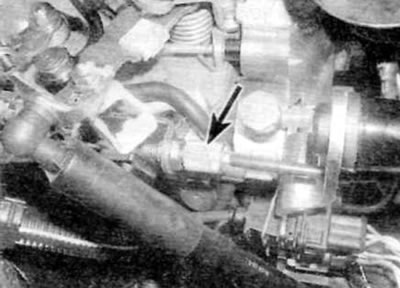
Pic. 10.13. High idle cable adjustment screw and locknut (models with 1.9 l engine)
14. Securely tighten the tip clamp screw/nut and adjuster locknut and measure the exposed length of the high idle cable.
15. Install the air inlet assembly (if it was removed see paragraph 3).
16. Charge the cooling system as described in chapter 1B, and let the engine run until it reaches normal operating temperature.
17. At normal operating temperature of the fuel, the thermostatic sensor cable should have slack, providing a play of approximately 0.5-1.0 mm. If there is no play in the cable, the sensor may be defective. If the thermostatic sensor is working properly, the cable should move at least 6mm when going from cold to hot.
18. Verify that the engine speed increases when the high idle lever is pushed towards the flywheel end of the engine.
19. If everything is in order, stop the engine and connect all relevant air lines.
20. Verify that all rubber mounts are properly seated, then install engine cover and secure with retainers.