
English Русский
Български
Беларускі
Український
Српски
Hrvatski
Română
Polski
Slovenský
Magyar
Bookmark Articles Sitemap Contacts
Company Hyundai Company Opel Company Skoda Company Kia Company Mitsubishi Company LADA Company Audi
PeugeotBook.ru


Series 100   Series 200   Series 300   400-500   Series 600   Crossovers   Others
 
Partner I (1996-2008) Peugeot 807 (2002-2014) Peugeot 806 (1994-2002) Peugeot J5 (1981-1993)

Accelerator cable — removal, installation and adjustment (Peugeot Partner I)

  • Main
  • Пежо
  • Partner I (1996-2008)
  • Power unit
  • Power and exhaust (DW diesels)
  • Accelerator cable — removal, installation and adjustment
0
Table of contents: Removal 🠇 Installation 🠇 Adjustment 🠇

Removal


Models with 1.9L engine


1. Remove the air intake duct as described in paragraph 3. Disconnect the accelerator cable from the accelerator lever on the high pressure fuel pump, and then pull the cable housing out of the support bracket along with the corresponding spring clip. While the cable is disconnected, to ensure safety, remove the cable mounting sleeve from the support bracket (Figure 4.1, a-c).
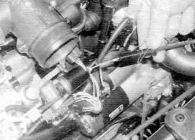
Figure 4.1, a. Disconnect the accelerator cable from the lever...
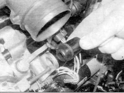
Figure 4.1, a. Disconnect the accelerator cable from the lever...


Figure 4.1, b....then remove the cable sheath together with the spring clamp from the pump bracket…

Figure 4.1, b....then remove the cable sheath together with the spring clamp from the pump bracket (models with a 1.9 L engine)
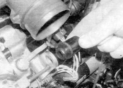

Figure 4.1, c. Remove the mounting sleeve from the pump while the cable is removed (models with a…

Figure 4.1, c. Remove the mounting sleeve from the pump while the cable is removed (models with a 1.9 L engine)


Models with a 2.0L engine produced before September 2002.


2. Remove the clips (turn them 90° to release) and remove the engine cover (figure 3.20, a, b).

3. Remove the two bolts and disconnect the accelerator pedal position sensor bracket from the air filter housing. Disconnect the accelerator cable from the sensor, then pull the cable housing out of the sensor bracket along with the spring clip (figure 4.3).
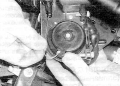
Figure 4.3. Disconnect the accelerator cable from the pedal position sensor (early models with a…

Figure 4.3. Disconnect the accelerator cable from the pedal position sensor (early models with a 2.0L engine)


Models with 2.0L engine produced after September 2002.


4. Disconnect the accelerator cable from the pedal position sensor located above the right engine/gearbox mount (figure 4.4).
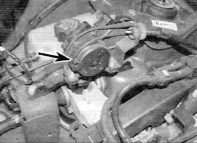
Figure 4.4. Disconnect the accelerator cable from the pedal position sensor (marked with an arrow)…

Figure 4.4. Disconnect the accelerator cable from the pedal position sensor (marked with an arrow) (later models with 2.0L engine)


5. Remove the cable sheath from the rubber bushing on the sensor bracket together with the spring clip.

All models


6. Follow the cable along its entire length and release it from all the clamps or ties one by one, noting how it is laid out.

7. Inside the vehicle, remove the fuse box cover and lower trim section from under the driver's side fascia.

8. Reach under the faceplate, squeeze the end of the cable and disconnect the cable from the top of the accelerator pedal. If applicable, remove the bulkhead seal retaining clip.

9. Tie a piece of fishing line to the end of the rope.

10. Go to the engine compartment, release the cable sealing grommet from the bulkhead and remove the cable. When the end of the rope appears, untie the line and leave it in place; it can be used to retract the cable during installation.

Installation


11. Tie a fishing line to the end of the rope, and then use the fishing line to pull the rope through the bulkhead. When the end of the cable appears, untie the fishing line and connect the cable to the pedal. If applicable, install the bulkhead grommet clamp.

12. Working from the engine compartment side, properly secure the cable housing into the bulkhead grommet, then route the cable correctly and secure it along its entire length using appropriate clamps and ties.

13. On 1.9L models, insert the mounting sleeve into the support bracket, then route the cable through the sleeve and connect it to the accelerator lever. Adjust the cable as described below, then install the instrument panel trim sections.


14. On 2.0L models, route the cable housing through the grommet in the support bracket and connect the cable to the accelerator pedal position sensor. If applicable, install the sensor bracket to the side of the air cleaner housing and securely tighten the associated bolts. Adjust the position of the cable as described below. Install the instrument panel trim sections.

Adjustment


15. On all models, remove the spring clip from the accelerator cable housing (figure 4.15). Move the high pressure fuel pump lever/accelerator pedal position sensor to the limit position and carefully pull the cable out of the corresponding sealing grommet until all slack in the cable is eliminated.

Original is contained on the portal peugeotbook
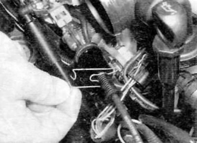
Figure 4.15. Remove the spring clip and adjust the accelerator cable (the model shown is one with a…

Figure 4.15. Remove the spring clip and adjust the accelerator cable (the model shown is one with a 1.9L engine)


16. While holding the cable in this position, install the spring clip into the last open groove on the cable sheath before the rubber grommet and washer. Once the clamp is installed and the cable sheath is released, the cable should have only a slight play.

17. Have an assistant depress the accelerator pedal and check that the accelerator lever/accelerator pedal position sensor moves to the fully open position and smoothly returns to the limit position.

18. Finally, install the engine cover and secure it with the clips.
This article is available at russian, bulgarian, belarusian, ukrainian, serbian, croatian, romanian, polish, slovak, hungarian
Article reviewed by editor: Nikonova Veronica
Share information:
Previous
Partner I: Power and exhaust (DW diesels)
Next

Air cleaner assembly and air intake ducts — removal and…
High Pressure Diesel Injection (HDi) System — special information
General information and precautions
Fuel and exhaust system specifications
Accelerator pedal — removal and installation
Fuel system — filling and bleeding
Low-pressure fuel pump (models with 2.0L engine) — removal and…
Fuel level indicator sensor — removal and installation
High Idle Speed Thermostatic Sensor (1.9L Engine Models)
See similar information for other Peugeot models

➨ Accelerator cable — removal, refitting and adjustment Peugeot 106 (1991-2003)
➨ Headlight adjustment Peugeot 207 (2006-2014)
➨ Carburetor — accelerator pump (checking and adjustment) Peugeot 305 (1977-1989)
➨ Accelerator cable — removal, installation and adjustment Peugeot 406 (1995-2004)
➨ High pressure fuel pump — removal, installation and adjustment Peugeot 605 (1989-2000)
Link to this article in different formats
Comments and feedback from visitors
No comments yet


Add two numbers 46 + 36


Partner I (1996-2008) 
  • General information
  • Introduction to the guide
  • Faults en route
  • Weekly checks
  • User manual
  • Maintenance (petrol)
  • Maintenance (diesel)
  • Power unit
  • Petrol engines
  • Diesel engines «XUD»
  • Diesel engines «DW»
  • Overhaul of petrol engines
  • Overhaul of diesel engines
  • Cooling and heating
  • Power and exhaust (petrol)
  • Power and exhaust (XUD diesels)
  • Power and exhaust (DW diesels)
  • Emission reduction
  • Starting and charging system
  • Transmission
  • Clutch
  • Mechanical gearbox
  • Drive shafts
  • Chassis, running gear
  • Brake system
  • Car suspension
  • Steering
  • Body and interior
  • Exterior (external elements)
  • Interior (internal elements)
  • Doors, locks and windows
  • Electrical equipment
  • Equipment and devices
  • Electrical circuits
Peugeot 807 (2002-2014) 
  • General information
  • Operating instructions
  • Maintenance
  • Troubleshooting
  • Power unit
  • Gasoline engines
  • Diesel engines
  • Cooling and heating
  • Fuel injection (petrol)
  • Fuel system (diesel)
  • Fuel system
  • Exhaust system
  • Ignition system
  • Transmission
  • Clutch
  • Manual gearbox
  • Automatic gearbox
  • Chassis, running gear
  • Brake system
  • Car suspension
  • Steering system
  • Body and interior
  • Exterior (external elements)
  • Interior (internal elements)
  • Electrical equipment
  • Power devices
  • Electrical circuits
Peugeot 806 (1994-2002) 
  • General information
  • User manual
  • Maintenance
  • Power unit
  • Petrol engines
  • Diesel engines
  • Lubrication system
  • Cooling system
  • Fuel injection (petrol)
  • Fuel system (diesel)
  • Ignition and exhaust systems
  • ECM Bosch Motronic MP 3.2
  • ECM Magneti-Marelli (MM)
  • Transmission
  • Clutch
  • Mechanical gearbox
  • Chassis, running gear
  • Brake system
  • Car suspension
  • Steering
  • Electrical equipment
  • Equipment and devices
  • Electrical circuits
Peugeot J5 (1981-1993) 
  • General information
  • Introduction to manual
  • Specifications
  • Gasoline engine
  • Engine repair
  • Lubrication system
  • Cooling system
  • Fuel system
  • Ignition system
  • Diesel engine
  • Engine repair (DB9)
  • Lubrication system (DB9)
  • Cooling system (DB9)
  • Fuel injection (DB9)
  • Engine repair (U25)
  • Lubrication system (U25)
  • Cooling system (U25)
  • Fuel injection (U25)
  • Transmission
  • Clutch
  • Gearbox
  • Drive shafts
  • Chassis, running gear
  • Steering system
  • Car suspension
  • Brake system
  • Electrical equipment
  • Power devices
  • Electrical circuits
PeugeotBook.ru © 2018–2026 | Mobile version | Sitemap: EN BG BY UA RS HR RO PL SK HU | Write message | Site search | Add to bookmarks | Peugeot owners
106 (1991-2003) | 206 (1998-2012) | 207 (2006-2014) | 305 (1977-1989) | 306 (1993-2002) | 307 (2001-2008) | 405 (1987-1997) | 406 (1995-2004) | 605 (1989-2000) | Partner-I (1996-2008) | Eurovans-807 (2002-2014) | Eurovans-806 (1994-2002) | J5 (1981-1993) |
Cookies are used to ensure the correct display of pages on the site.