
Removal - 1.9L Engine Models
Models with WJZ engine
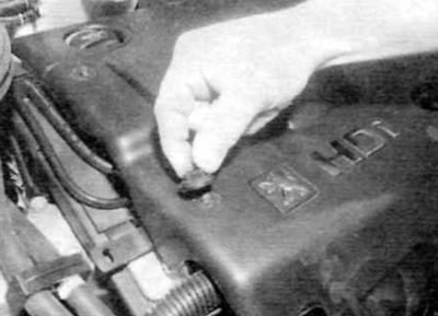
1. Release the fasteners on the right side and the top plane of the engine cover, and then carefully, so as not to lose the rubber supports, remove the cover (pic. 3.1, a-c).
Pic. 3.1, a. Remove the clips on the right side...
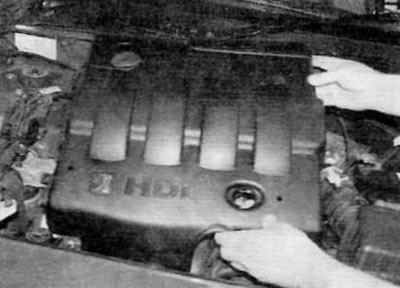
Pic. 3.1b....and from the top plane of the engine cover
Pic. 3.1, c....then remove the engine cover (models 1.9 l)
2. Turn out two bolts of fastening of an inlet air line to the forward panel of a body. Release a collar, disconnect an air line from the air filter and remove it from the car.
3. Loosen the clamps securing the intake air duct to the air filter cover and the EGR valve body. Remove the mounting bolt at the base of the resonator, and then disconnect the air line and remove it from the engine.
4. Turn out a bolt of fastening of the basis of the case of the air filter to a basic arm. Lift the body, release the front dowel pins and remove the body from the vehicle.
Models with WJY engine built before September 2002
5. Release the latches on the right side and the top plane of the engine cover, and then carefully, so as not to lose the rubber supports, remove the cover (pic. 3.1, a-c).
6. Disconnect the ground wire from the battery (see «Disconnecting the battery» in the application).
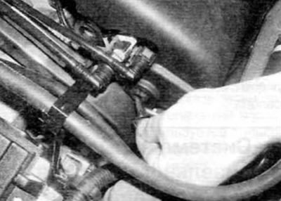
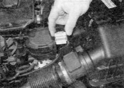
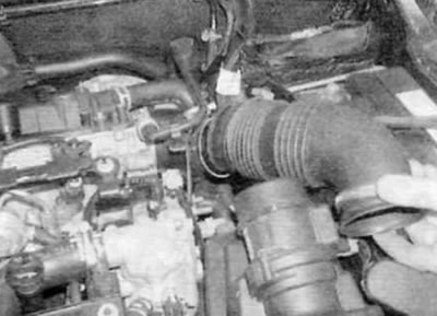
7. Release the clips securing the intake air duct to the air flow sensor on the air filter cover and to the EGR valve body. Unscrew the bolt at the base of the resonator, then disconnect the air line and remove it from the engine (pic. 3.7, a-c).
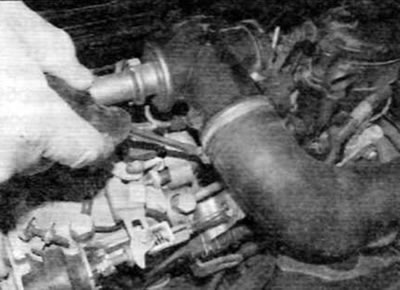
Pic. 3.7, a. Release the yoke (marked with an arrow) fastening the intake air duct to the air flow sensor...
Pic. 3.7b....and to the EGR valve body...
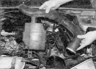
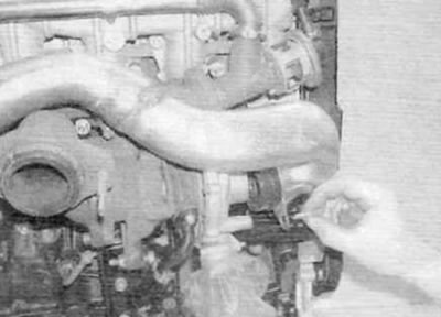
Pic. 3.7, c - then unscrew the resonator mounting bolt and remove the air duct from the engine (early models with 1.9L engine)
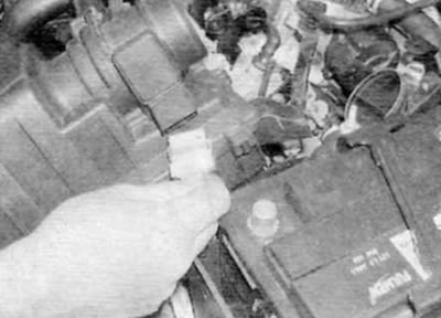
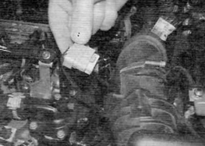
8. Disconnect the electrical connector of the air flow sensor mounted on the air filter cover (fig.3.8).
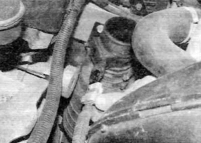
Pic. 3.8. Disconnect the air flow sensor electrical connector (early models with 1.9L engine)
9. Turn out the screw of fastening of an inlet air line to the forward panel of a body (pic. 3.9). Slightly move the air duct to the side to release the additional lock.
Pic. 3.9. Remove the screw securing the intake air duct to the front panel of the body (early models with 1.9L engine)
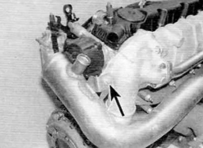
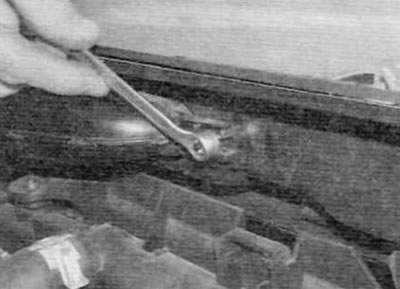
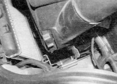
10. Turn out a bolt of fastening of the top basic arm of the air filter to a side member of a body (pic. 3.10).
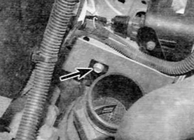
Pic. 3.10. Remove the bolt (marked with an arrow) fastening the upper support bracket of the air filter to the side member of the body (early models with 1.9L engine)
11. Fully apply the parking brake. Raise the front of the vehicle and securely jack stands under it (see «Lifting and placing the car on supports»).
12. Remove the left wheel and turn out the screws securing the front section of the wheel arch locker to the bumper and front fender.
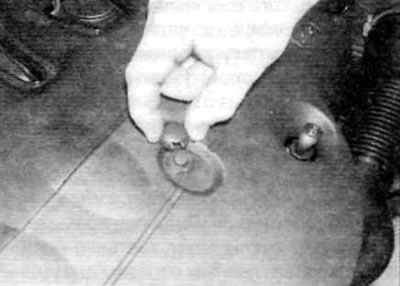
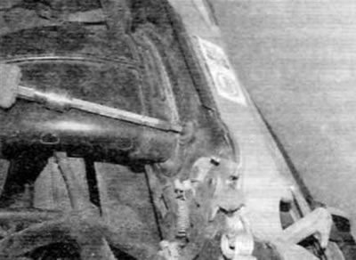
13. Remove the locker from its original position. then unscrew the two lower nuts securing the air filter (pic. 3.13). Lift the air filter and air intake duct out of the engine compartment. If necessary, loosen the clamp and separate the intake air line from the air filter housing. Models with a WJY engine manufactured after September 2002
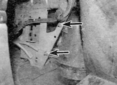
Pic. 3.13. Air filter bottom nuts (marked with arrows) (early models with 1.9L engine)
14. Release the latches on the right side and the top plane of the engine cover, and then carefully, so as not to lose the rubber supports, remove the cover (pic. 3.1. a-c).
15. Turn away a nut of fastening of an inlet air line to the forward panel of a body (pic. 3.15). Remove the air line from the support pin and move it slightly to the side to release the additional retainer.
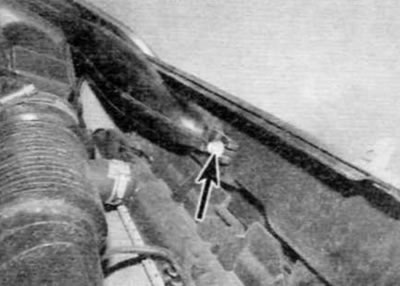
Pic. 3.15. Loosen the nut (marked with an arrow) attaching the intake air duct to the front panel of the body (late models with 1.9 l engine)
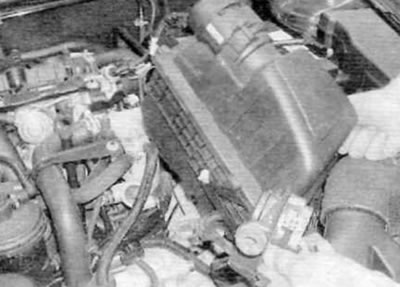
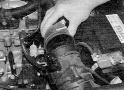
16. Remove the air line from the base of the air filter and remove it from the vehicle (pic. 3.16).
Pic. 3.16. Remove the air line from the base of the air filter and remove it from the vehicle (late models with 1.9 l engine)
17 Disconnect the electrical connector for the air flow sensor located on the side of the air filter cover (pic. 3.17).
Pic. 3.17. Disconnect the air flow sensor electrical connector (late models with 1.9 l engine)
18. Release the clamp securing the intake air duct to the EGR valve body and unscrew the mounting bolt at the base of the resonator.
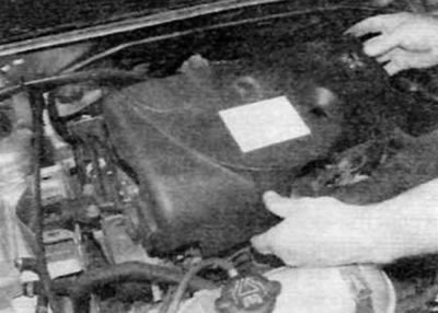
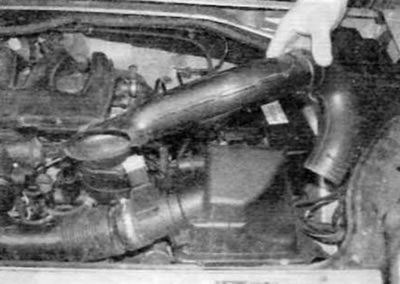
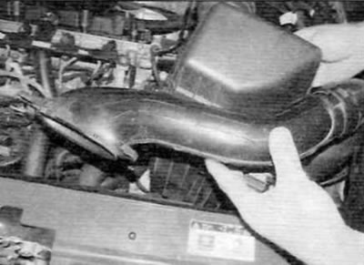
19. Remove the air line from the EGR valve body and unhook the air filter housing from the support bracket. Remove the air line and air filter housing from the engine compartment as a single piece (pic. 3.19).
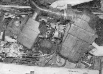
Pic. 3.19. Remove the air filter housing and air duct from the engine compartment as a single element (late models with 1.9 l engine)
Removal - 2.0L Models
Release models prior to September 2002
20. Remove the clips (turn them 90°to release) and remove the engine cover (pic. 3.20, a, b).
Pic. 3.20 a. To release, turn each lock 90°...
Pic. 3.20 b....and remove the engine cover (models with 2.0 l engine)
21. Release the clips and disconnect the flexible air line from the air flow sensor and the turbocharger rigid intake air line (pic. 3.21). Properly plug the turbocharger hard intake air line with a clean rag to prevent dirt and other foreign material from getting inside.
Pic. 3.21. Disconnect the flexible air line from the air flow sensor in the rigid intake air line of the turbocharger (early models with 2.0L engine)
22. Turn out two bolts and release an arm of the gauge of position of a pedal of an accelerator from a lateral party of the case of the air filter.
23. Disconnect the air flow sensor electrical connector on the side of the air filter cover. Remove the air filter housing assembly from the appropriate support bracket and remove it from the engine compartment (pic. 3.23, a, b).
Pic. 3.23 a. Disconnect the air flow sensor electrical connector...
Pic. 3.23b....then lift the rear of the air filter housing and release the front mounting tabs (early models with 2.0L engine)
24. For removal of an inlet air line release a clip and disconnect an air line from an inlet branch pipe on the front panel of a body. Remove the bolts securing the air duct to the air filter support bracket and remove the air duct from the engine compartment.
25. The rigid air lines at the rear of the engine connecting the turbocharger to the flexible intake air line and intake manifold are not accessible until the engine is removed from the vehicle. Access will require either removing the engine/gearbox assembly as described in chapter 2D, or remove the front suspension subframe as described in chapter 10.
26. Once you have gained access, begin removing the turbocharger rigid intake air line by disconnecting the crankcase ventilation system hose at the top of the air line.
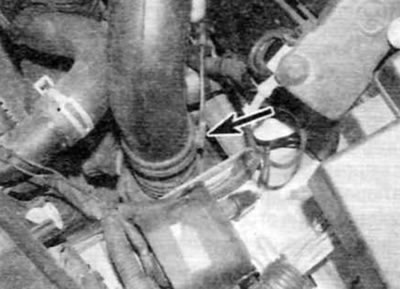
27. Turn out a bolt of fastening of an air line to an elbow branch pipe of an inlet collector (pic. 3.27).
Pic. 3.27. Remove the top bolt (marked with an arrow) attaching a rigid intake air duct to the intake manifold (early models with 2.0L engine)
28. Turn out the bottom bolt of fastening of an air line to a turbocharger (pic. 3.28). Remove the air line, and then remove the seal from its lower end.
Pic. 3.28. Turn out a bolt of fastening of a rigid inlet air line to a turbocharger and remove an air line (early models with 2.0L engine)
29. To remove the hard plastic air line between the turbocharger and the intake manifold, loosen the clamp and disconnect the connecting hose from the intake manifold elbow.
30. Release a collar of fastening of a connecting hose on the lower end of the air line going to a turbocharger. Disconnect the connecting plate from the ledge on the turbocharger and remove the air line from the engine.
Release models after September 2002
31. Remove the clips (turn them 90°to release) and remove the engine cover (pic. 3.20 a. b).
32. Turn away a nut of fastening of an inlet air line to the forward panel of a body (pic. 3.32). Remove the air line from the support pin and move it slightly to the side to release the additional retainer.
Pic. 3.32. Loosen the nut securing the intake air duct to the front panel of the body (late models with 2.0 l engine)
33. Disconnect the air flow sensor electrical connector on the back of the air filter cover (pic. 3.33).
Pic. 3.33. Disconnect the air flow sensor electrical connector (late models with 2.0 l engine)
34. Release the clamp and disconnect the flexible intake air line from the air flow sensor (pic. 3.34).
Pic. 3.34. Loosen the clamp and disconnect the flexible intake air line from the air flow sensor (late models with 2.0 l engine)
35. Unhook the air filter housing from the support bracket. Remove the air filter housing and air duct from the engine compartment as a single element (pic. 3.35, a, b).
Pic. 3.35 a. Unhook the air filter housing from the appropriate support bracket...
Pic. 3.35 b....then remove the air filter housing and intake duct as one piece (late models with 2.0 l engine)
36. To remove the rigid air ducts on the back of the engine, proceed as described in p.p. 25-30 above.
Installation
37. Installation is carried out in the reverse order of removal. Ensure that all hoses and air lines are properly connected, properly installed and securely fastened with appropriate clamps or bolts.