



Table of contents: Models with 1.9L engine 🠇 Models with a 2.0L engine 🠇
Warning. Be careful when performing this procedure to prevent dirt from entering the high pressure fuel pump or injector fuel lines.
Models with 1.9L engine
Note: If the high pressure fuel pump is being sent to a fuel injection specialist for repair, unlock the immobilizer module as described below before disconnecting the battery. Turn on the ignition and open the driver's door window. Exit the vehicle and close all doors, then turn off the ignition. After reaching through the window, turn the ignition back on, wait at least 10 seconds, and then turn the ignition off. Immediately disconnect the ground wire from the battery (see "Disconnecting the battery") and disconnect the electrical connectors on the high-pressure fuel pump (the pump must be disconnected within 10 minutes after turning off the ignition). If the immobilizer module is not unlocked, the pump repair technician will not be able to test the pump.
Removal
1. Disconnect the ground cable from the battery (see "Disconnecting the battery").
2. Release the fasteners on the right side and the top plane of the engine cover, and then carefully, so as not to lose the rubber supports, remove the cover (Figure 3.1, a-c).
3. Remove the air intake duct connecting the air filter to the EGR valve body (see paragraph 3).
4. Cover the components under the high pressure fuel pump with a plastic bag as a precaution in case of fuel spillage.
5. Remove the high pressure fuel pump sprocket as described in paragraph 9 of chapter 2B.
6. Remove the upper section of the intake manifold (see paragraph 17).
7. Disconnect the accelerator cable from the high-pressure fuel pump (see paragraph 4).
8. Disconnect the high idle speed cable from the high pressure fuel pump (see paragraph 10).
9. Trace the high pressure fuel pump fuel supply line to the filter. Wipe the line fitting clean, then loosen and disconnect the line from the filter. Cap the end of the line and the fitting on the filter housing to minimize fuel leakage and prevent dirt from entering the system.
10. Wipe clean the area around the high pressure fuel pump metal return line fittings. Disconnect the return line and hose from the metal line and plug the ends of the line and fitting to minimize fuel leakage and prevent dirt from entering the system.
11. Disconnect the electrical connectors of the high-pressure fuel pump (figure 13.11).
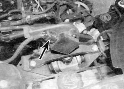
Figure 13.11. Disconnect the electrical connectors (marked with arrows) on the back of the high pressure pump (later models with 1.9L engine)
12. Remove all traces of dirt from the fittings of all fuel injector lines. Loosen the union nuts securing the fuel lines to the injectors, the high-pressure fuel pump, and the injectors. Hold the fittings on the pump while loosening the union nuts securing the lines to the pump. Remove the fuel lines as a set. Cap the injector/high pressure fuel pump connections to prevent dirt from entering.
13. Loosen the rear pump mounting bolt.
14. Remove the three front bolts securing the pump to the support bracket, and then remove the pump from its standard position.
15. If necessary, unscrew the pump support bracket mounting bolt and remove it from the cylinder head, making sure not to lose the mounting pins.
Installation
16. If necessary, replace the dowel pins and install the support bracket onto the cylinder head. Tighten the bracket mounting bolts to the specified torque.
17. Properly install the rear pump mounting bolt, spacer, washer and nut onto the support bracket.
18. Install the pump in its original place and position it correctly in the support bracket.
19. Install the front pump mounting bolts and tighten them to the specified torque. After tightening the front bolts, tighten the rear bolt to the specified torque.
20. Install and connect the fuel injector lines. Pre-tighten all union nuts to ensure all fuel lines are properly seated, then tighten them to the specified torque in the same sequence. Hold the fittings on the high pressure fuel pump while tightening the nuts on the pump side.
21. Connect the corresponding electrical connectors on the pump.
22. Securely connect the supply and return lines to the high pressure fuel pump and to the fuel filter housing.
23. Connect and adjust the accelerator cable as described in paragraph 4.
24. Connect and adjust the high idle speed cable as described in paragraph 10.
25. Install the high pressure fuel pump sprocket and put on the timing belt as described in chapter 2B.
26. Install the intake manifold as described in paragraph 17.
27. Fill the fuel system as described in paragraph 6. Start the engine and check for any signs of fuel leaks before installing the engine cover.
Models with a 2.0L engine
Note: Installation will require a new high pressure fuel line installed between the fuel pump and the fuel rail.
Removal
28. Disconnect the ground cable from the battery (see "Disconnecting the battery").
29. Remove the high pressure fuel pump sprocket as described in paragraph 9 of chapter 2B.
30. Disconnect the quick release couplings of the fuel supply and return hoses at the top of the fuel pump, using a screwdriver to release the retaining clip. Seal open connections appropriately to prevent dirt from entering.
31. Similarly, disconnect the quick-release couplings of the supply and return fuel hoses on the fuel filter and plug the open connections. Release the fuel hoses (and on later models, a booster pump) from the corresponding clamps.
32. Remove the fuel filter from its support bracket and move it slightly away from the pump.
33. Remove the bolts and the filter support bracket from the engine.
34. Remove the bolts securing the plastic wiring harness guide to the front of the engine. To access the rear of the fuel pump, you will need to lift the wiring harness as much as possible. If necessary, disconnect the appropriate electrical connectors so that the wiring harness assembly can be moved away from the guide for further ease of access.
35. Disconnect the electrical connector from the pressure control valve on the rear of the fuel pump and from the piston cut-off switch on the top of the pump.
36. Thoroughly clean the high-pressure fuel line fittings on the fuel pump and fuel rail. Using an open-end wrench, loosen the union nuts securing the high-pressure fuel lines to the fuel pump and fuel rail. When loosening the union nuts, hold the fittings on the pump and fuel rail with a second wrench. Remove the high pressure fuel line and plug any open connections to prevent dirt from entering (figure 13.36). Please note that installation will require a new high pressure fuel line.
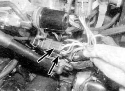
Figure 13.36. High-pressure fuel pump (models with a 2.0 L engine)
1. High pressure pipeline
2. High pressure fuel regulator electrical connector
3. Bolts for fastening the rear bracket to the pump
4. Bolts for fastening the rear bracket to the support bracket
5. Rear bracket
6. Return fuel hose
7. Front pump mounting nuts/bolts
8. Fuel supply hose
9. Electrical connector of the third piston shut-off solenoid valve
10. Fuel line fitting
37. Loosen the nut and remove the bolt securing the rear support of the fuel pump to the support bracket.
38. Remove the nut and two bolts securing the front part of the fuel pump to the support bracket. Remove the pump along with the fuel supply and return hoses and remove it from the engine.
Warning. The high pressure fuel pump is manufactured to very tight tolerances and should never be disassembled under any circumstances. Do not unscrew the male fuel line fitting on the back of the pump or attempt to remove the pressure control valve, piston cut-off switch, or seal on the pump shaft. Pump components are not supplied separately, and if there is a suspicion that the pump is faulty, it should be replaced.
Installation
39. Install the pump on the support bracket, tighten the nut and screw in the two bolts that secure the pump to the front. Install the nut and bolt that secures the fuel pump rear support to the support bracket, then tighten all bolts/nuts to the specified torque.
40. Remove the plugs from the fuel line fittings on the pump and fuel rail. Attach the new high pressure fuel line to the fittings and at this stage tighten the union nuts by hand.
41. Using a torque wrench and a special adapter, tighten the fuel line union nuts to the specified torque. When tightening the union nuts, hold the fittings on the pump and fuel rail with an open-end wrench (figure 13.41).
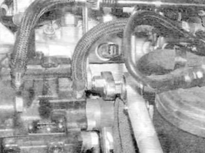
Figure 13.41. When connecting a new high-pressure fuel line to the pump and fuel rail, hold the corresponding fittings while tightening the union nuts to the specified torque (models with a 2.0 L engine)
42. Connect the electrical connector of the pressure control valve to the rear of the fuel pump.
43. Replace and secure the plastic wiring harness guide on the front of the engine and reconnect all remaining wiring that was disconnected for ease of access.
44. Install the filter support bracket onto the engine and tighten the bolts securely. Position the fuel filter in the proper position on the support bracket.
45. Remove the plugs and connect the quick release couplings of the supply and return hoses at the fuel filter and at the connections on the top of the fuel pump. Secure the hoses with appropriate clamps.
46. Install the high pressure fuel pump sprocket and put on the timing belt as described in chapter 2B.
47. Observing the precautions described in paragraph 2, fill the fuel system as described in paragraph 6. Then start the engine and allow it to idle. Check high pressure fuel line connections for leaks while the engine is idling. If everything is OK, increase the engine speed to 4000 rpm and check for leaks again. Take the vehicle for a short road test and check for leaks again upon return. If leaks are detected, purchase and install a new high-pressure fuel line. Do not attempt to fix even the smallest leak by tightening the fuel line fittings
48. Finally, install the engine cover.