
Models with 1.9L WJZ engine
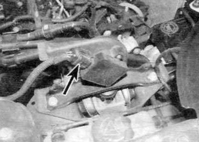
Stop solenoid valve
1. The stop solenoid valve is part of the immobilizer; it is located on top of the high pressure fuel pump. It is designed to turn off the fuel supply when the ignition is turned off. Replacing the immobilizer/solenoid valve is a complex operation that should be left to a Peugeot/Citroen dealer or a diesel injection specialist. The immobilizer is fixed with shear bolts, which must be drilled out (This is a dangerous operation which, if not performed carelessly, may result in damage to). When installing, you must perform the procedure for initializing a new block.
Inertial fuel switch
Note. The inertial fuel switch is not available on all models.
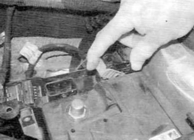
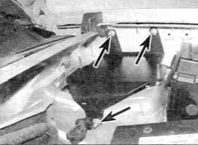
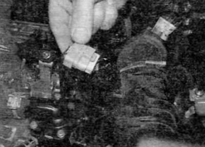
2. The inertial fuel supply switch is located in the right rear corner of the engine compartment. Remove it, and first disconnect the ground wire from the battery (see «Disconnecting the battery»).
3. Turn out bolts, then disconnect an electric socket and remove the switch from the car.
4. Installation is carried out in the reverse order of removal. Finally, reconfigure the switch by firmly pressing the button on its top.
Models with 1.9L WJY engine
Stop solenoid valve
5 See point 1.
Electronic control unit (release models before September 2002)
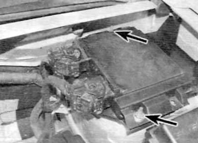
6. BEU is located in a plastic box, which is part of the rear section of the battery shelf. On some engines, access to the nuts/bolts securing the BEU is difficult, and it is recommended to first remove the battery shelf, as described in chapter 5A, and then on the workbench remove the BEU from the shelf.
7. Disconnect the ground wire from the battery (see «Disconnecting the battery»).
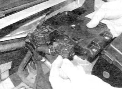
8. If applicable, remove the cover from the ECU, and then lift the locking latches and disconnect the electrical connectors of the ECU (pic. 12.8).
Pic. 12.8. Raise the locking latches and disconnect the electrical connectors of the BEU (early models with 1.8L engine)
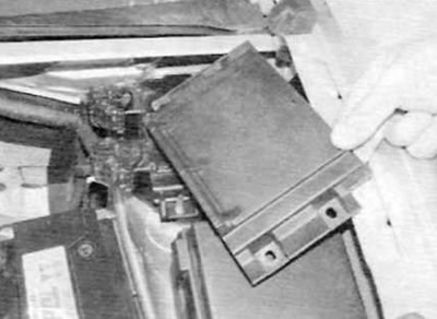
9. Remove the nuts or bolts and remove the BEU support plate from the battery shelf.
10. Turn away nuts or turn out bolts and separate BEU from a basic plate.
11. Installation is carried out in the reverse order of removal. Securely dock the electrical connectors of the BEU.
Electronic control unit (release models after September 2002)
12. The BEU is located in the left rear corner of the engine compartment, above the upper support of the suspension strut.
13. Disconnect the ground wire from the battery (see «Disconnecting the battery»).
14. Unscrew the nuts and remove the BEU cover. if applicable (pic. 12.14, a, b).
Pic. 12.14 a. Loosen the nuts (marked with an arrow)...
Pic. 12.14, b....and remove the BEU cover (late models with 1.8 l engine)
15. Lift the BEU and remove it from the support bracket, and then lift the locking latches and disconnect the electrical connectors (pic. 12.15).
Pic. 12.15. Remove the BCU from the support bracket, and then disconnect the electrical connectors (late models with 1.9 l engine)
16. If necessary, after unscrewing the three fastening nuts, you can remove the support bracket (pic. 12.16).
Pic. 12.16. BZU support bracket mounting bolts (marked with an arrow) (late models with 1.9 l engine)
17. Installation is carried out in the reverse order of removal. Connect electrical connectors securely.
Air flow sensor (release models before September 2002)
18. Disconnect the ground wire from the battery (see «Disconnecting the battery»).
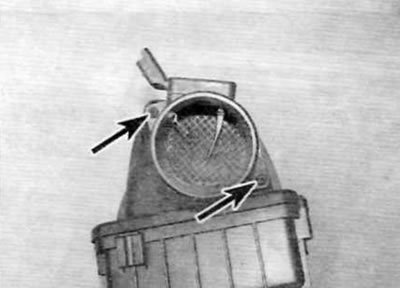
19. Release a collar of fastening of an inlet air line to the gauge of the expense of air on a cover of the air filter. Disconnect the air line from the air flow sensor.
20. Disconnect the air flow sensor electrical connector (pic. 12.20).
Pic. 12.20. Disconnect the air flow sensor electrical connector (early models with 1.9L engine)
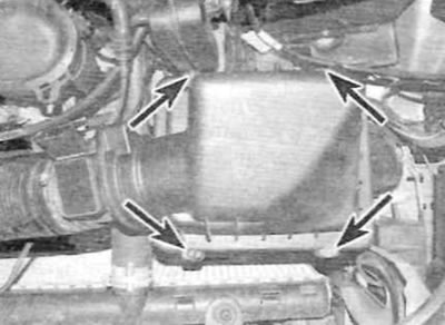
21. Release the clamp securing the air flow sensor to the air filter cover and remove the sensor (pic. 12.21).
Pic. 12.21. Loosen the clamp and remove the air flow sensor (early models with 1.9L engine)
22. Installation is carried out in the reverse order of removal. Connect the electrical connector securely.
Air flow sensor (release models after September 2002)
23. Disconnect the ground wire from the battery (see «Disconnecting the battery»).
24. Release a collar of fastening of an inlet air line to the gauge of the expense of air on a cover of the air filter.
25. Disconnect the electrical connector of the air flow sensor (pic. 12.25).
Pic. 12.25. Disconnect the air flow sensor electrical connector (late models with 1.9 l engine)
26. Remove the four screws securing the cover to the air filter housing (pic. 12.26). Remove the cover and disconnect the intake air line.
Pic. 12.26. Remove four screws (marked with arrows) fixing the cover to the air filter housing (late models with 1.9 l engine)
27. Remove the two screws securing the air flow sensor to the air filter cover and remove the sensor from the cover (pic. 12.27).
Pic. 12.27. Remove two screws (marked with arrows) and remove the air flow sensor from the air filter cover (late models with 1.9 l engine)
28. Installation is carried out in the reverse order of removal. Connect the electrical connector securely.
Crankshaft sensor
29. The crankshaft sensor is located on top of the gearbox.
30. To remove the sensor, first disconnect the ground wire from the battery (see «Disconnecting the battery»).
31. Disconnect the sensor electrical connector, and then release the bolt and remove the sensor from the gearbox (the sensor has a groove for easy removal) (pic. 12.31 a.m. b).
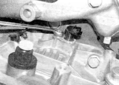
Pic. 12.31 a.m. Loosen the bolt...
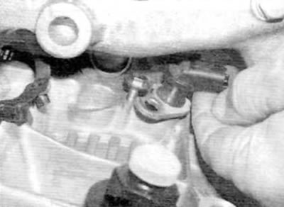
Pic. 12.31 b.... and then remove the crankshaft sensor from under the bolt and remove it
32. Installation is carried out in the reverse order of removal.
Vehicle speed sensor
33. The vehicle speed sensor is an integral part of the speedometer drive. For details on installation and removal, see chapter 7.
Nozzle needle lift sensor
34. The injector needle lift sensor is an integral part of the No. 1 cylinder injector. For removal and installation details, refer to paragraph 15.
Coolant temperature sensor
35. The coolant temperature sensor is screwed into the thermostat/fuel filter housing. For installation and removal information, see chapter 3.
Potentiometer «throttle valve» and injection advance solenoid valve
36. Both of these elements are located on the high pressure fuel pump. If any of these elements is defective, the replacement should be carried out by a Peugeot/Citroen dealer who has the necessary special equipment to adjust and calibrate the elements.
Inertial fuel switch
Note. The inertial fuel switch is not available on all models.
37. Proceed as described in paragraphs 2-4.
Models with 2.0L engine
Electronic control unit
38. Proceed as described in paragraphs 6-17.
Crankshaft sensor
39. Proceed as described in paragraphs 29-32. Access to the sensor is difficult; remove the battery and battery tray for easier access (see chapter 5A).
Vehicle speed sensor
40. The vehicle speed sensor is an integral part of the speedometer drive. For details on installation and removal, see chapter 7.
Coolant temperature sensor
41. The coolant temperature sensor is mounted on the side of the thermostat/coolant outlet housing at the left end of the cylinder head. For installation and removal information, see chapter 3.
Air flow sensor
42. Disconnect the ground wire from the battery (see «Disconnecting the battery»).
43. Disconnect the electrical connector of the air flow sensor located on the air filter cover (pic. 12.43).
Pic. 12.43. Disconnect the air flow sensor electrical connector (models with 2.0 l engine)
44. Release a collar and disconnect an inlet air line from the gauge of the expense of air.
45. Turn out two screws of fastening of a cover to the case of the air filter. Lift the right side of the cover and unhook the two left locking tabs from the air filter housing (pic. 12.45, a, b).
Pic. 12.45 a.m. Loosen the air filter cover screws...
Pic. 12.45, b - release the two tabs and remove the cover from the air filter housing (models with 2.0 l engine)
46. Remove the two screws securing the air flow sensor to the air filter cover and remove the sensor from the cover.
47. Installation is carried out in the reverse order of removal. Connect the electrical connector securely.
Camshaft position sensor
48. The camshaft position sensor is located on the cylinder head cover at the top right. Before removal, disconnect the ground wire from the battery (see «Disconnecting the battery»). Remove the clips (turn them 90°to release) and remove the engine cover (pic. 3.20, a, b).
49. Remove the upper timing belt cover (see chapter 2B).
50. Disunite an electric socket of the gauge of a camshaft.
51. Turn out a bolt and remove the gauge from the engine.
52. When installing, align the locating hole in the camshaft hub with the locating hole in the cylinder head (see paragraph 3 of chapter 2B). Insert the flywheel locking tool to make sure the camshaft is properly positioned.
53. Install the sensor on the support bracket and lightly tighten the bolt.
54. If a new sensor is being installed, position the sensor so that its mounting tab is in contact with the rear of the camshaft hub, and then securely tighten the sensor bolt. The lug automatically sets the correct sensor air gap and will be broken the first time the engine is started.
55. If a previously removed sensor is installed, using a set of feelers, set a gap of 1.2 mm between the tip of the sensor and the camshaft hub. Make sure the sensor is properly positioned and then securely tighten the sensor mounting bolt (pic. 12.55). Check the air gap and adjust if necessary.
56. With the sensor correctly aligned, install the timing belt cover and remove the flywheel locking tool (if installed).
57. Dock the electrical connector of the sensor and connect the ground wire to the battery. Install the engine cover.
Fuel temperature sensor
Attention! Before starting work, please refer to the precautions described in paragraph 8.
Note. Do not remove the sensor from the fuel rail unless there is a valid reason to do so. At the time of writing, there is no information available regarding the acquisition of the sensor seal as a separate item. Please contact your Peugeot/Citroen dealer for the latest information before starting work.
58. The fuel temperature sensor is located closer to the right end of the fuel rail (pic. 12.58). Before removal, disconnect the ground wire from the battery (see «Disconnecting the battery»).
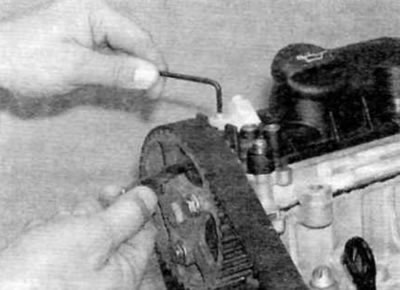
Pic. 12.55. Adjust the air gap of the camshaft position Danes (models with 2.0 l engine)
59. Remove the clips (turn them 90°to release) and remove the engine cover (pic. 3.20, a, b).
60. Disunite an electric socket of the gauge of temperature of fuel.
61. Thoroughly clean the area around the sensor and its location on the fuel rail.
62. Suitably cover the elements under the sensor and prepare a sufficient amount of clean rags. Be prepared for a significant amount of fuel to escape.
63. Remove the bolt and remove the sensor from the fuel rail. After removing the sensor, plug the hole in the fuel rail.
64. Before installation, if a previously removed sensor must be replaced, replace the sensor seal (if applicable) (see note at the beginning of this subsection).
65. Insert the sensor into the fuel rail and securely tighten the bolt.
66. Dock the electrical connector of the sensor and connect the battery.
67. By observing the precautions described in paragraph 2, fill the fuel system as described in paragraph 6. Then start the engine and allow it to idle. Check the fuel temperature sensor for leaks while the engine is idling. If everything is in order, increase the engine speed to 4000 rpm and check for leaks again. Carry out a short road test of the vehicle and check for leaks again upon return. If leaks are found, purchase and install a new sensor.
68. Finally, install the engine cover.
Fuel pressure sensor
Attention! Before starting work, refer to the precautions described in paragraph 8.
Note. This procedure will require a 27mm yoke adapter and a new sensor O-ring.
69. The fuel pressure sensor is located centrally on the underside of the fuel rail (pic. 12.58).
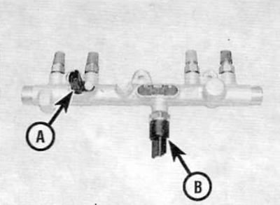
Pic. 12.58. Location of fuel temperature sensor (A) and fuel pressure sensor (IN) on the fuel rail (for clarity, the ramp is shown removed) (models with 2.0 l engine)
70. Disconnect the ground wire from the battery (see «Disconnecting the battery»). Then remove the fasteners (turn them 90°to release) and remove the engine cover (pic. 3.20, a, b).
71. Release the clamp and disconnect the crankcase ventilation hose from the cylinder head cover.
72. Disconnect the fuel supply and return fuel hose quick fittings at the fuel filter. To do this, use a small screwdriver to release the locking clip. Seal open connections appropriately to prevent dirt from entering. Release the fuel hoses from their respective clamps.
73. Disunite an electric socket of the gauge of pressure of fuel.
74. Thoroughly clean the area around the sensor and its location on the fuel rail.
75. Suitably cover the elements under the sensor and prepare a sufficient amount of clean rags. Be prepared for a significant amount of fuel to escape.
76. Using a 27mm yoke adapter and socket extension, unscrew the fuel pressure sensor from the base of the fuel rail.
77. Purchase and install a new O-ring on the sensor prior to installation.
78.Install the sensor on the fuel rail and tighten to the specified torque.
79. Dock the electrical connector of the sensor, connect the fuel hoses, the crankcase ventilation hose and the battery.
80. By observing the precautions described in paragraph 2, fill the fuel system as described in paragraph 6. Then start the engine and let it idle. Check the fuel temperature sensor for leaks while the engine is idling. If everything is in order, increase the engine speed to 4000 rpm and check for leaks again. Carry out a short road test of the vehicle and check for leaks again upon return. If leaks are found, purchase and install a new sensor O-ring.
81. Finally, install the engine cover.
3rd Piston Shut Off Solenoid Valve
82. The solenoid valve is located on top of the high pressure fuel pump. It is an integral part of the pump and cannot be replaced. If the valve is defective, the high pressure fuel pump must be replaced or repaired. Never attempt to remove the solenoid valve from the pump.
High pressure fuel regulator
83. The high pressure fuel regulator is located on the back of the high pressure fuel pump. It is an integral part of the pump and cannot be replaced. If the regulator is defective, the high pressure fuel pump must be replaced or repaired. Never attempt to remove the regulator from the pump.
Inertial fuel switch
84. Act as described in paragraphs 2-4.
Electric fuel heater
Attention! Before starting work, refer to the precautions described in paragraph 8.
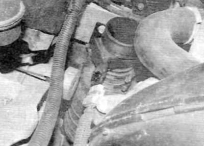
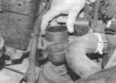
85. An electric fuel heater is located on the fuel supply line leading to the filter housing (pic. 12.85).
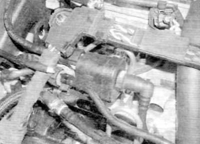
Pic. 12.85. Fuel heater assembly (models with 2.0 l engine)
86. Disconnect the ground wire from the battery (see «Disconnecting the battery»). Then remove the fasteners (turn them 90°to release) and remove the engine cover (pic. 3.20 a. b).
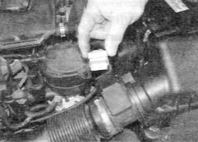
87. Disconnect the heater electrical connector.
88. Remove all traces of dirt from the area around the heater. Clean and dry the heater and adjacent area before proceeding. Place a rag under the heater to collect spilled fuel.
89. Release the clamps and disconnect the fuel lines from the heater. Plug the fuel lines to prevent dirt from entering the fuel system.
90. Turn out a bolt and remove a heater of fuel from the engine.
91. Installation is carried out in the reverse order of removal. Finally, fill the fuel system as described in paragraph 5.
Accelerator pedal position sensor (release models before September 2002)
92. From the side of the engine compartment, remove the two bolts and remove the accelerator pedal position sensor bracket from the side of the air filter housing.
93. Disconnect the electrical connector of the sensor (pic. 12.93).
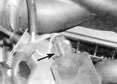
Pic. 12.93. Disconnect the electrical connector (marked with an arrow)...
94. Unhook the accelerator cable from the sensor cam, then release the cable sheath along with the spring clip from the sensor bracket and remove the sensor from the vehicle (pic. 12.94).
Pic. 12.94.... then disconnect the cable and remove the accelerator pedal position sensor from the vehicle (models with 2.0 l engine)
95. Installation is carried out in the reverse order of removal. Adjust the accelerator cable as described in paragraph 4.
Accelerator pedal position sensor (release models after September 2002)
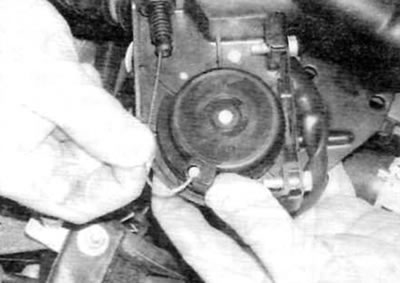
96. The accelerator pedal position sensor is located above the right engine/transmission mount.
97. Disconnect the ground wire from the battery (see «Disconnecting the battery»). Disconnect the pedal position sensor electrical connector (pic. 12.97).
Pic. 12.97. Disconnect the electrical connector (marked with an arrow) accelerator pedal position sensor (late models with 2.0 l engine)
98. Release the accelerator cable from the sensor cam, and then pull the cable sheath along with the spring clip from the rubber bushing of the support bracket.
9.9 Remove the two support bracket mounting bolts and remove the pedal position sensor and support bracket from the engine compartment.
100. Remove the two nuts and bolts securing the sensor to the support bracket and separate the two elements.
101. Installation is carried out in the reverse order of removal. Finally, adjust the accelerator cable as described in paragraph 4.