



Table of contents: Models with gasoline engine 🠇 Models with 1.8L and 1.9L diesel…🠇 Models with a 2.0L diesel engine 🠇
Models with gasoline engine
Cooling Fan Switch - Early Models
1. On models without air conditioning, the cooling fan switch has a blue electrical connector and is located on the left side of the radiator.
2. On models with air conditioning, the cooling fans are controlled by the air conditioning control unit using signals from the temperature sensor located on the top of the thermostat housing. The sensor can be identified by its brown electrical connector.
Overheating warning lamp switch/temperature gauge sensor
3. The overheat warning light switch/temperature gauge sensor has a blue electrical connector and is located in the thermostat housing or on the left end of the cylinder head.
Engine coolant temperature sensor
4. The coolant temperature sensor has a green electrical connector and is located in the thermostat housing.
[Information posted on the website www.PEUGEOTBOOK.ru]
5. On later engines (starting around 2001) the coolant temperature sensor has a blue or green electrical connector and is located above the thermostat in the coolant distribution housing on the left end of the cylinder head (figure 6.5). The temperature signal from this sensor is used by the engine control unit to set fuel injection/ignition timing advance and control the operation of the cooling fan, air conditioning system and overheating warning lamp/temperature gauge.
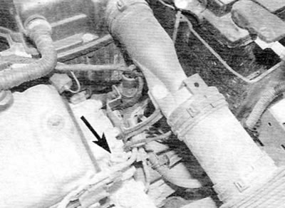
Figure 6.5. Engine coolant temperature sensor (marked with an arrow) on later models with a 1.4L petrol engine
Models with 1.8L and 1.9L diesel engines
Cooling fan switch
6. On models without air conditioning, the cooling fan switch has a blue electrical connector and is located on the left side of the radiator.
7. On models with air conditioning, the cooling fans are controlled by the air conditioning control unit using signals from the temperature sensor located in the thermostat housing. The sensor can be identified by its brown electrical connector. Overheating warning lamp switch/temperature gauge sensor
8. The overheat warning light switch/temperature gauge sensor has a blue electrical connector and is located in the thermostat housing.
Coolant Temperature Switch/Sensor for Glow Plug/Exhaust Gas Recirculation (EGR) System
9. The coolant temperature sensor, used to control the pre-heating and EGR system, has a green electrical connector and is located in the thermostat housing.
Models with a 2.0L diesel engine
Engine coolant temperature sensor
10. On 2.0L diesel engines, the coolant temperature sensor has a green electrical connector and is mounted in the thermostat/coolant distribution housing on the left end of the cylinder head. The temperature signal from this sensor is used by the engine control unit to control diesel fuel injection and to operate the exhaust gas recirculation system, cooling fans, pre-heating/post-heating control unit, air conditioning and overheating warning lamp/temperature gauge.
Removal
Caution: Allow the engine to cool before removing the cooling system switch/sensor.
11. Disconnect the ground cable from the battery (see "Disconnecting the Battery" in the Appendix).
12. Partially drain the cooling system to a level just below the switch/sensor (as described in Chapter 1A or 1B). Alternatively, prepare a suitable plug to seal the switch hole in the housing after removing the switch. If you intend to use a plug, be very careful not to allow dirt to enter the cooling system.
13. If necessary, to facilitate access to switches/sensors located in the thermostat housing or cylinder head, refer to chapter 4A, 4B or 4B and remove the air filter assembly and air intake ducts.
14. Disconnect the electrical connector of the corresponding switch/sensor.
15. On later engines equipped with a plastic thermostat/coolant distribution housing, remove the sensor retaining ring, then remove the sensor and O-ring from the housing (figure 6.15). If the system has not been drained, plug the sensor hole to prevent further coolant leakage.
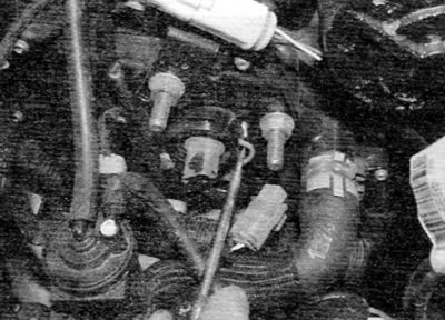
Figure 6.15. On later models, remove the sensor retaining ring, then remove the sensor and O-ring from the housing
16. On all other engines, carefully unscrew the switch/sensor from its support and remove the O-ring (if applicable). If the system is not drained, plug the switch/sensor hole to prevent further coolant leakage.
Installation
17. On models equipped with a plastic thermostat/coolant distribution housing, install a new O-ring onto the sensor. Press the sensor firmly into the housing and secure it with the retaining ring, making sure that it fits correctly into the groove in the housing. Connect the electrical connector of the sensor.
18. On all other engines, if the switch/sensor was installed using sealant, thoroughly clean the switch/sensor threads and apply fresh sealant to the threads. If the switch was installed using an O-ring, use a new O-ring during installation.
19. Install the switch/sensor, tighten it securely and connect the electrical connector.
20. On all engines, fill the cooling system and bleed air from the system as described in Chapter 1A or 1B. Follow the bleeding instructions carefully to ensure all air is removed from the cooling system.
21. Finally, reinstall all components removed for access, then start the engine and allow it to run until it reaches normal operating temperature. With the engine running, check that the element controlled by the switch/sensor is operating properly.