



Table of contents: Heating/ventilation system control…🠇 Heating/Ventilation control cables 🠇 Heater radiator 🠇 Heater electric fan 🠇
Heating/ventilation system control unit
Removal
1. Disconnect the ground cable from the battery (see "Disconnecting the battery").
2. To access the control unit, remove the corresponding panels in the center of the front panel as described in chapter 11.
3. Remove the two top mounting screws at each corner of the control unit
4. Using a small screwdriver, release the latch at the bottom center of the control unit and remove the unit from the front panel (figure 10.4).
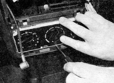
Figure 10.4. Release the latch at the bottom center of the heating/ventilation control unit and remove the unit from the front panel
5. Rotate the control unit upward as far as space allows, then release the clamps and disconnect the control cables from the unit. Mark the location of the cables to ensure proper installation (figure 10.5).
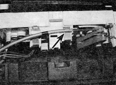
Figure 10.5. Rotate the control unit upward and then release the clamps (marked with arrows) and disconnect the control cables
6. Disconnect the electrical connector on the back of the control unit, and then remove the unit.
Installation
7. Installation is performed in the reverse order of removal. Connect the control cables properly according to their original position.
Heating/Ventilation control cables
Removal
8. When removing the control unit, disconnect the cables from the heating/ventilation control unit as described earlier in this paragraph.
9. Working through the hole in the faceplate or from underneath the faceplate (depending on which cable needs to be removed, it may be necessary to remove some sections of the faceplate to gain access (see chapter 11), release the clamps and disconnect the cable from the heater assembly. Mark the cable routing to ensure proper installation.
Installation
10. Installation is carried out in the reverse order of removal. Route the cables correctly and secure them securely.
Heater radiator
Note: New O-rings must be used for the heater hose fitting during installation.
Note: Heater design and layout vary significantly depending on model, engine type and year of manufacture. The following procedure applies to a typical case.
Removal
11. Drain the coolant from the cooling system (see chapter 1A or 1B).
12. Remove the front panel assembly as described in chapter 11.
13. While working in the engine compartment, disconnect the heater hoses from the heater lines. If the hoses are connected separately, release the clamps and disconnect the hoses from the heater core line fittings on the engine compartment bulkhead. If the hoses are connected to a block connector, remove the metal clip from the top of the connector, then release the plastic clip by pushing it towards the left hose connection. Pull the fitting out of the heater core. Remove the O-rings from the connector and discard them; when installing, new ones should be used (Figure 10.13, a-g).
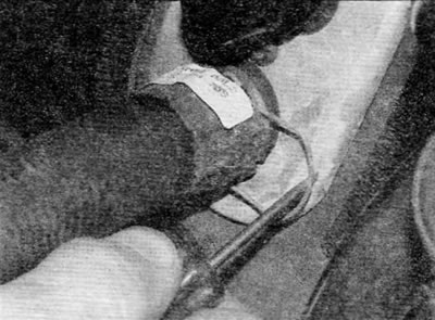
Figure 10.13, a. If the heater hoses are connected separately, remove the clamp and disconnect the hoses from the heater radiator pipe fittings
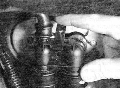
Figure 10.13, b. If the hoses are connected to a block connector, remove the metal clamp from the heater core connector...
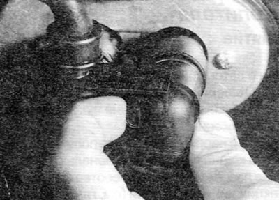
Figure 10.13, c....and then release the plastic clamp...
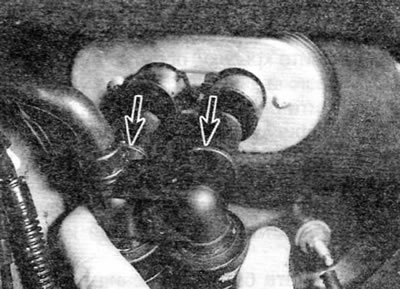
Figure 10.13, d....and separate the connector from the partition; remove the sealing rings (marked with arrows)
14. Remove the two screws securing the cover above the sealing bushing in the bulkhead for the heater radiator pipes. Remove the cover, paying attention to the D-shaped notch.
15. Remove the rubber sealing bushing for fixing in the partition from the heater radiator pipes.
16. Working inside the vehicle, disconnect and remove the air vent ducts on the driver and passenger sides.
17. Remove the bolt securing the heater base to the bracket on the floor (figure 10.17).
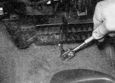
Figure 10.17. Remove the bolt securing the lower part of the heater to the bracket on the floor
18. Make sure all cables, wires and related components are disconnected or moved to the side to allow the heater to be moved into the vehicle interior.
19. Working in the engine compartment again, unscrew the two nuts securing the heater assembly to the bulkhead.
20. Call an assistant and, working from the engine compartment, release the heater radiator pipes from the bulkhead and pull the heater assembly into the vehicle interior.
21. With the heater assembly removed, release the four clamps and then remove the heater core from the heater housing (figure 10.21).
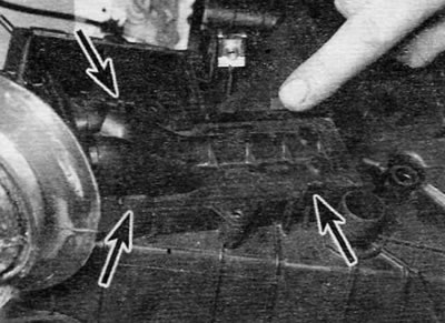
Figure 10.21. Release the four clamps (marked with arrows), and then remove the heater core from the heater housing
Installation
22. Installation is carried out in the reverse order of removal, taking into account the following points:
- a) Before installing the heater assembly, lubricate the sealing sleeve of the heater pipes, and then install it on the heater pipes.
- b) Bring the heater assembly into its normal position and at the same time insert the sealing bushing of the heater pipes into the partition (and again ask an assistant to help you from the engine compartment).
- c) When connecting the heater hoses to the pipes, install new O-rings on the heater core pipes, and then connect the hose fittings to the pipes.
Heater electric fan
Removal
23. The electric fan assembly is located in the vehicle on the passenger side.
24. Disconnect the ground cable from the battery (see "Disconnecting the Battery" in the Appendix).
25. If necessary, remove the appropriate sections of the front panel to gain access to the area under the passenger side dashboard (see chapter 11).
26. Loosen the screws securing the electric motor assembly to the heater assembly and remove the electric motor from its standard location with a downward movement (figure 10.26).
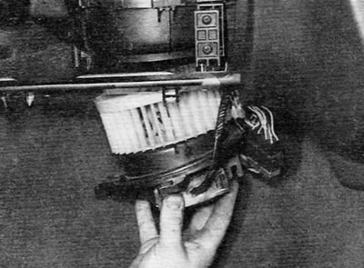
Figure 10.26. Loosen the screws securing the electric motor to the heater and remove the electric motor from its standard location
27. Cut the cable that secures the electrical wiring to the engine cover, then pull out the rubber grommet and disconnect the electrical connector.
Installation
28. Installation is carried out in the reverse order of removal.