
English Русский
Български
Беларускі
Український
Српски
Hrvatski
Română
Polski
Slovenský
Magyar
Bookmark Articles Sitemap Contacts
Company Hyundai Company Opel Company Skoda Company Kia Company Mitsubishi Company LADA Company Audi
PeugeotBook.ru


Series 100   Series 200   Series 300   400-500   Series 600   Crossovers   Others
 
Partner I (1996-2008) Peugeot 807 (2002-2014) Peugeot 806 (1994-2002) Peugeot J5 (1981-1993)

Front Panel Elements (Produced After September 2002) — removal and installation (Peugeot Partner I)

  • Main
  • Пежо
  • Partner I (1996-2008)
  • Body and interior
  • Interior (internal elements)
  • Front Panel Elements (Produced After September 2002) — removal and installation
0
Table of contents: Steering column covers 🠇 Instrument panel 🠇 Multifunctional display 🠇 Central sections of the front panel 🠇 Front panel assembly 🠇

Steering column covers


Removal


1. Remove the three screws securing the bottom casing.

2. Remove the lower cover, then lift and remove the upper cover (figure 31.2).
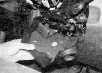
Figure 31.2. Remove the lower steering column cover, then lift and remove the upper cover

Figure 31.2. Remove the lower steering column cover, then lift and remove the upper cover


Installation


3. Installation is performed in the reverse order of removal.

Instrument panel


4. Contact chapter 12.

Multifunctional display


5. Refer to Chapter 12.

Central sections of the front panel


Removal


6. Carefully remove the multifunction display frame from the front panel (figure 31.6).
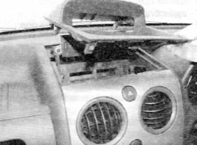
Figure 31.6. Carefully remove the multifunction display frame from the front panel

Figure 31.6. Carefully remove the multifunction display frame from the front panel


7. Carefully lift the center switch panel away from the faceplate to release the top clips (figure 31.7).
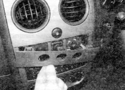
Figure 31.7. Carefully lift the center switch panel away from the faceplate to release the top clips

Figure 31.7. Carefully lift the center switch panel away from the faceplate to release the top clips


8. Remove the audio unit as described in chapter 12.

9. Remove the two screws above the audio unit opening (figure 31.9).
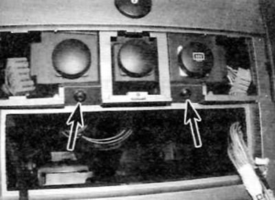
Figure 31.9. Remove two screws (marked with arrows) above the opening for the audio unit

Figure 31.9. Remove two screws (marked with arrows) above the opening for the audio unit


10. Remove the two screws in the multifunction display opening (figure 31.10).
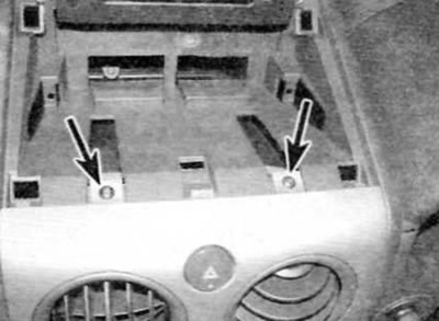
Figure 31.10. Remove two screws (marked with arrows) in the opening for the multifunctional display

Figure 31.10. Remove two screws (marked with arrows) in the opening for the multifunctional display


11. Carefully remove the center panel from the front panel to release the side clips and remove the panel from the vehicle (figure 31.11).
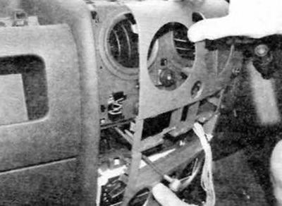
Figure 31.11. Carefully remove the center panel from the front panel to release the side clips

Figure 31.11. Carefully remove the center panel from the front panel to release the side clips


Installation


12. Installation is performed in the reverse order of removal.

Front panel assembly


Note: This is a complex operation requiring the removal of numerous components and assemblies and the disconnection of numerous electrical connectors. Mark the location of all disconnected electrical wiring accordingly or attach labels to the connectors to avoid confusion during installation.


Removal


13. Disconnect the ground cable from the battery (see "Disconnecting the battery").

14. Remove the hood grille panel as described in paragraph 24.

15. Remove the windshield wiper motor and linkage as described in chapter 12.

16. Through the opening for the hood grille panel, unscrew the three nuts securing the front panel to the partition.

17. Move the front seats all the way back. Set the steering wheel to the straight ahead position and lock the steering column lock.

18. Remove the steering column covers and upper section of the fascia as described earlier in this paragraph.


19. Remove the front pillar trim panels as described in paragraph 28.

20. Remove the center console as described in paragraph 29.

(Article based on material from the website: Peugeotbook.ru)

21. Remove the bottom covers from under the front panel on both sides.

22. Remove the steering wheel as described in chapter 10.

23. Remove the following items as described in chapter 12:
  • a) instrument panel:
  • b) audio block;
  • c) passenger airbag:
  • d) steering column switches;
  • d) multifunctional display.

24. Remove all front panel switches as described in chapter 12.

25. Remove the tweeters from the top of the front panel as described in chapter 12.

26. Remove the bolts on each side at the edges of the front panel.

27. Remove the two top screws in each corner of the heater/ventilation control unit.

28. Using a small screwdriver, release the locking tab at the bottom center of the control unit and remove the unit from the front panel.

29. Rotate the control unit upward as far as space allows, then release the clamps and disconnect the control cables from the unit. Mark the location of the cables to ensure proper installation.

30. Disconnect the electrical connector on the back of the control unit, and then remove the unit.

31. Remove all bolts/screws securing the front panel.

32. Remove the fuse box cover and release the fuse/relay box from its mounting hardware in the faceplate.

33. Remove the bolt and release the hood release handle.

34. Disconnect or release all remaining faceplate fasteners.

35. With the help of an assistant, lift the front panel above the installation site and slide it back. Once sufficient space has been created, disconnect all electrical connectors from the front panel, noting their installation positions. Note the wiring harness routing and release it from the various clamps.


36. Make sure that. that all necessary components are disconnected and moved to the side, and then remove the front panel from the car.

Installation


37. Installation is performed in sequence. reverse of removal. Ensure all electrical connectors are properly connected and the corresponding bolts/nuts are securely tightened.
This article is available at russian, bulgarian, belarusian, ukrainian, serbian, croatian, romanian, polish, slovak, hungarian
Article reviewed by editor: Nikonova Veronica
Share information:
Previous
Partner I: Interior (internal elements)
Next

Front panel components (manufactured before September 2002) —…
Center console — removal and installation
Interior trim — removal and installation
Seat belt components — removal and installation
Seats — removal and installation
 
See similar information for other Peugeot models

➨ Front brake pad check Peugeot 106 (1991-2003)
➨ Replacing the upper front part of the control panel Peugeot 207 (2006-2014)
➨ Removal and installation front disc brake pads on models… Peugeot 305 (1977-1989)
➨ Front Panel Replacement — Removal, Repair and Installation Peugeot 405 (1987-1997)
➨ Instrument panel Peugeot 605 (1989-2000)
Link to this article in different formats
Comments and feedback from visitors
No comments yet


Add two numbers 13 + 45


Partner I (1996-2008) 
  • General information
  • Introduction to the guide
  • Faults en route
  • Weekly checks
  • User manual
  • Maintenance (petrol)
  • Maintenance (diesel)
  • Power unit
  • Petrol engines
  • Diesel engines «XUD»
  • Diesel engines «DW»
  • Overhaul of petrol engines
  • Overhaul of diesel engines
  • Cooling and heating
  • Power and exhaust (petrol)
  • Power and exhaust (XUD diesels)
  • Power and exhaust (DW diesels)
  • Emission reduction
  • Starting and charging system
  • Transmission
  • Clutch
  • Mechanical gearbox
  • Drive shafts
  • Chassis, running gear
  • Brake system
  • Car suspension
  • Steering
  • Body and interior
  • Exterior (external elements)
  • Interior (internal elements)
  • Doors, locks and windows
  • Electrical equipment
  • Equipment and devices
  • Electrical circuits
Peugeot 807 (2002-2014) 
  • General information
  • Operating instructions
  • Maintenance
  • Troubleshooting
  • Power unit
  • Gasoline engines
  • Diesel engines
  • Cooling and heating
  • Fuel injection (petrol)
  • Fuel system (diesel)
  • Fuel system
  • Exhaust system
  • Ignition system
  • Transmission
  • Clutch
  • Manual gearbox
  • Automatic gearbox
  • Chassis, running gear
  • Brake system
  • Car suspension
  • Steering system
  • Body and interior
  • Exterior (external elements)
  • Interior (internal elements)
  • Electrical equipment
  • Power devices
  • Electrical circuits
Peugeot 806 (1994-2002) 
  • General information
  • User manual
  • Maintenance
  • Power unit
  • Petrol engines
  • Diesel engines
  • Lubrication system
  • Cooling system
  • Fuel injection (petrol)
  • Fuel system (diesel)
  • Ignition and exhaust systems
  • ECM Bosch Motronic MP 3.2
  • ECM Magneti-Marelli (MM)
  • Transmission
  • Clutch
  • Mechanical gearbox
  • Chassis, running gear
  • Brake system
  • Car suspension
  • Steering
  • Electrical equipment
  • Equipment and devices
  • Electrical circuits
Peugeot J5 (1981-1993) 
  • General information
  • Introduction to manual
  • Specifications
  • Gasoline engine
  • Engine repair
  • Lubrication system
  • Cooling system
  • Fuel system
  • Ignition system
  • Diesel engine
  • Engine repair (DB9)
  • Lubrication system (DB9)
  • Cooling system (DB9)
  • Fuel injection (DB9)
  • Engine repair (U25)
  • Lubrication system (U25)
  • Cooling system (U25)
  • Fuel injection (U25)
  • Transmission
  • Clutch
  • Gearbox
  • Drive shafts
  • Chassis, running gear
  • Steering system
  • Car suspension
  • Brake system
  • Electrical equipment
  • Power devices
  • Electrical circuits
PeugeotBook.ru © 2018–2026 | Mobile version | Sitemap: EN BG BY UA RS HR RO PL SK HU | Write message | Site search | Add to bookmarks | Peugeot owners
106 (1991-2003) | 206 (1998-2012) | 207 (2006-2014) | 305 (1977-1989) | 306 (1993-2002) | 307 (2001-2008) | 405 (1987-1997) | 406 (1995-2004) | 605 (1989-2000) | Partner-I (1996-2008) | Eurovans-807 (2002-2014) | Eurovans-806 (1994-2002) | J5 (1981-1993) |
Cookies are used to ensure the correct display of pages on the site.