
Note. Before removing any switch, disconnect the wire «masses» from the battery and connect this wire after setting the switch. Cm. «Disconnecting the battery».
Ignition switch
1. See chapter 10.
Steering column switches
Release models prior to September 2002
2. Remove the steering wheel as described in chapter 10.
3. Remove the lower and upper steering column covers as described in chapter 11.
4. On models equipped with airbags, remove the airbag coil spring electrical connector as described in paragraph 21.
5. Disunite electric sockets on a back part of switches of a steering column.
6. Turn out three screws of fastening of the case of the switch to a steering column and remove the case from a column.
7. After unscrewing the two screws, the corresponding switch can be removed from the housing.
8. Installation is carried out in the reverse order of removal.
Release models after September 2002
9. Remove the steering wheel as described in chapter 10.
10. Remove the lower and upper casings of the steering column, as described in chapter 11.
11. Release the switch assembly retaining clip, then use a small screwdriver to gently pry the latches away from the column and remove the switch assembly. Disconnect the electrical connectors when removing the switch (pic. 4.11, a-d).
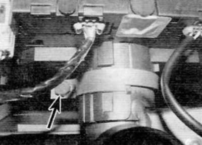
Pic. 4.11, a. Release the retaining clip of the switch assembly (marked with an arrow)...
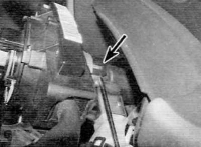
Pic. 4.11b.... carefully remove the latches (marked with arrows) away from the column...
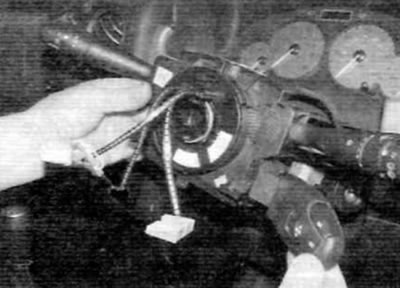
Pic. 4.11, c....and remove the switch assembly (later models)
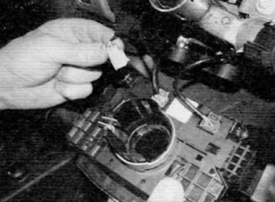
Pic. 4.11, d. Turn the unit over and disconnect the electrical connectors (later models)
Warning. Be extremely careful not to damage the switch assembly latches.
12. If necessary, you can disconnect the audio unit remote control switch from the main switch.
13. Installation is carried out in the reverse order of removal.
Note. If a new switch is installed, it must be initialized using the special test equipment. Have this job done by a Peugeot/Citroen dealer or a person with the appropriate equipment.
Switches mounted in the center of the front panel
Release models prior to September 2002
14. Using a small screwdriver, carefully remove the trim panel to gain access to the switches (pic. 4.14).
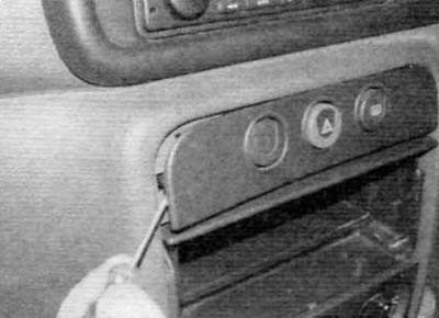
Pic. 4.14. Carefully remove the trim panel to gain access to the switches (early models)
15. Press the locking tabs on the side of the switch housing and remove the corresponding switch (pic. 4.15 a. b). Disconnect the electrical connector and remove the switch.
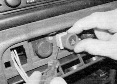
Pic. 4.15 a. Push in the locking tabs on the side of the switch housing...
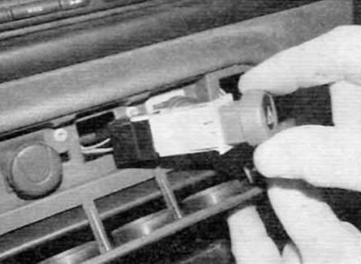
Pic. 4.15b....and remove the corresponding switch (early models)
16. Installation is carried out in the reverse order of removal.
Release models after September 2002
17. To gain access to the switches, remove the trim panels in the center of the bezel as described in chapter 11.
18. To remove the bottom switches, reach through the opening for the audio unit or through the opening on the side of the switch and push the corresponding switch out of the faceplate (pic. 4.18). Disconnect the electrical connector and remove the switch.
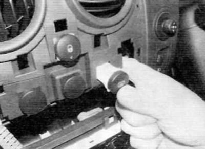
Pic. 4.18. To remove the lower switches, insert your hand into the opening on the front panel and push the switch out (later models)
19. To remove the top switches, press the tabs on the top of the switch housing and remove the switch from the faceplate (pic. 4.19). Disconnect the electrical connector and remove the switch.
Pic. 4.19. To remove the top switches, press the locking tabs and remove the switch (later models)
20. Installation is carried out in the reverse order of removal.
Switches mounted on the side of the front panel
21. On pre-September 2002 models, the auxiliary switches are located above the fuse box on the driver's side.
22. Using a small screwdriver, carefully remove the trim panel around the switch box. Remove the screw (-s) and remove the switch block from the front panel. Disunite electric sockets and remove the block. Switch (-And) can be pushed out from the back of the panel.
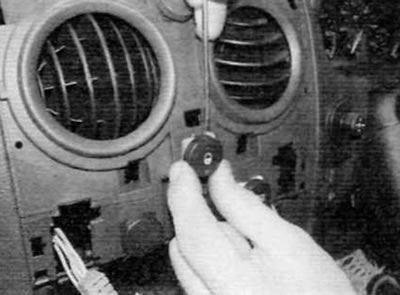
23. On models after September 2002, additional switches are located in the front panel next to the heater/ventilation air ducts. Using a small screwdriver, carefully pry out the corresponding switch. Disconnect the electrical connector and remove the switch.
24. Installation is carried out in the reverse order of removal.
Heating/ventilation control switches
25. These switches are an integral part of the heating/ventilation control panel and cannot be replaced individually. If any switch is defective, the entire control panel must be replaced (for details, please refer to chapter 3).
Stoplight switch
26. Refer to chapter 9.
Parking brake warning light switch
27. Refer to chapter 9.
Interior light switch
28. Interior light switches are an integral part of door locks. For details on removing and installing the door lock, refer to chapter 11.