



Table of contents: General information 🠇 Headlights 🠇 Front parking lights 🠇 Front direction indicators 🠇 Side turn signal repeaters 🠇 Fog lights 🠇 Taillights assembly 🠇 High-mounted brake light 🠇 Models with a double-leaf tailgate 🠇 License plate lights 🠇 Models with a double-leaf tailgate 🠇
General information
1. When replacing any lamp, please keep the following points in mind:
- a) Remember that if the light has just been turned off, the lamp may be very hot.
- b) Be sure to check the contacts of the lamp and its socket. There should be a clean, metal-to-metal contact between the lamp base and the socket contacts. Remove any traces of corrosion or dirt before installing the new lamp.
- c) In cases where lamps with bayonet-type bases are used (see "Specifications") Be sure to check the tightness of the contact between the lamp base and the socket contacts.
- d) Before installing a new lamp, be sure to check its power. It is necessary to make sure that the lamp is clean. This is especially true for headlight/fog light bulbs (see below).
Headlights
Models produced before September 2002.
2. In the engine compartment, disconnect the electrical connector on the back of the headlight bulb, and then remove the protective rubber cover from the headlight (figure 5.2).
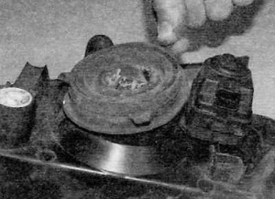
Figure 5.2. Remove the protective rubber cover from the headlight (early models)
3. Release the spring clip and remove the lamp (figure 5.3, a, b).
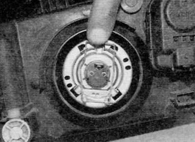
Figure 5.3, a. Release the spring clamp...
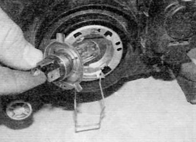
Figure 5.3, b....and remove the lamp (early models)
4. When handling a new lamp, use a clean cloth to avoid touching the lamp bulb with your fingers. Moisture and oil present on human skin can cause this type of lamp to turn black and burn out quickly. If you do accidentally touch the lamp, wipe it clean with a clean cloth soaked in denatured alcohol.
5. Install the new bulb, making sure that the mounting tabs fit correctly into the cutouts in the headlight housing. Secure the lamp with the spring clip.
6. Install the protective rubber cover. Make sure it is installed correctly. Then connect the electrical connector.
Models produced after September 2002.
7. In the engine compartment, turn the large plastic cover counterclockwise and remove it from the back of the headlight (figure 5.7).
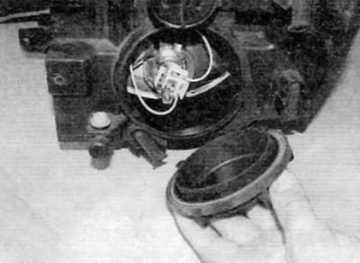
Figure 5.7. Remove the plastic cover from the headlight (late models)
[Source of the article is website: www.PeugeotBook.ru]
8. Disconnect the electrical connector on the back of the headlight (figure 5.8).
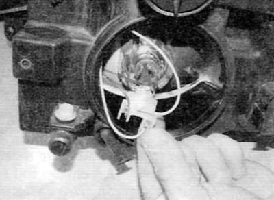
Figure 5.9. Disconnect the headlight bulb electrical connector (late models)
9. Release the spring clip and remove the lamp (figure 5.9, a, b).
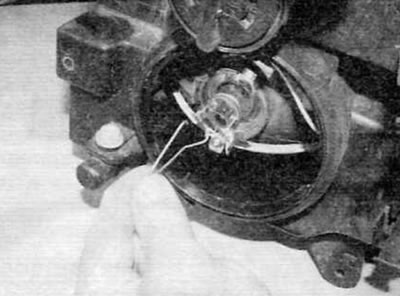
Figure 5.9, a. Release the spring clamp...
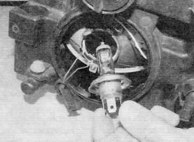
Figure 5.9, b....and remove the headlight bulb (late models)
10. When handling a new lamp, use a clean cloth to avoid touching the lamp bulb with your fingers. Moisture and oil present on human skin can cause this type of lamp to turn black and burn out quickly. If you do accidentally touch the lamp, wipe it clean with a clean cloth soaked in denatured alcohol.
11. Install the new bulb, making sure that the mounting tabs fit correctly into the cutouts in the headlight housing. Secure the lamp with the spring clip.
12. Connect the electrical connector, then install the plastic cover by turning it clockwise to lock it.
Front parking lights
Models produced before September 2002.
13. Open the hood and use a screwdriver to press on the tab located on the top of the turn signal (figure 5.13). Remove the turn signal.
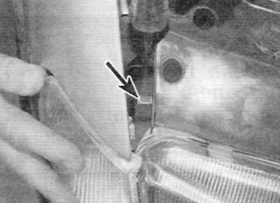
Figure 5.13. Press the tab (marked with an arrow) and remove the turn signal (early models)
14. Disconnect the electrical connector of the parking light socket (figure 5.14).
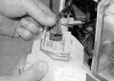
Figure 5.14. Disconnect the electrical connector on the parking light bulb socket (early models)
15. Turn the bulb holder counterclockwise and release it from the rear of the turn signal. The lamp is inserted into the lamp socket with a tight fit (figure 5.15, a, b).
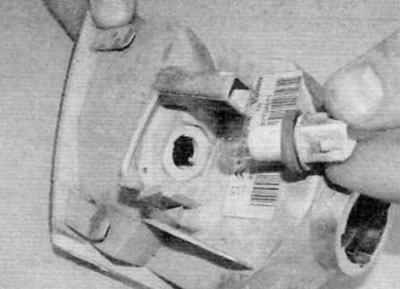
Figure 5.15, a. Turn the parking light bulb socket counterclockwise to release it
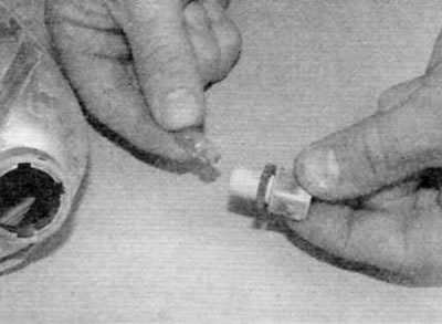
Figure 5.15, b. The lamp is installed in the socket with a tight fit (early models)
16. Install the lamp holder and turn it clockwise to lock it in place. Then connect the electrical connector.
17. Install the direction indicator. Make sure the top and bottom guides are properly secured.
Models produced after September 2002.
18. In the engine compartment, turn the large plastic cover counterclockwise and remove it from the back of the headlight (figure 5.7). The parking light bulb socket is located above the headlight bulb. For easier access, remove the headlight bulb as described above.
19. Remove the parking light bulb socket from the mounting hole in the headlight housing (figure 5.19). The lamp is inserted into the lamp socket with a tight fit.
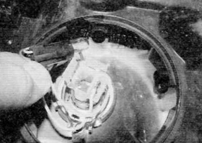
Figure 5.19. Pull the parking light bulb socket out of the mounting hole in the headlight housing (late models)
20. Install the bulb holder and headlight bulb (if it was removed).
21. Replace the plastic cover and turn it clockwise to lock it in place
Front direction indicators
Models produced before September 2002.
22. Open the hood and use a screwdriver to press on the tab located on the top of the turn signal (figure 5.13). Remove the turn signal.
23. Turn the bulb holder counterclockwise and release it from the rear of the turn signal. The lamp has a bayonet connection with the socket (figure 5.23, a, b).
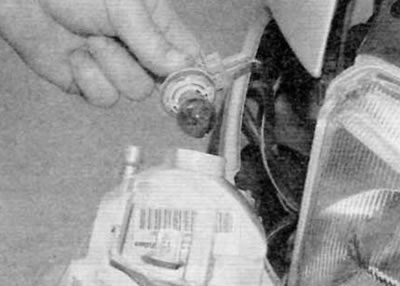
Figure 5.23, a. Turn the turn signal bulb socket counterclockwise to release it
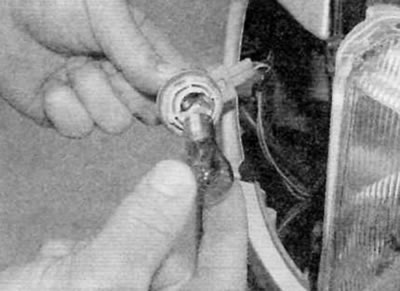
Figure 5.23, b. The lamp has a bayonet connection with the socket(early models)
24. Install the direction indicator. Make sure the top and bottom guides are properly secured.
Models produced after September 2002.
25. In the engine compartment, turn the turn signal bulb socket counterclockwise and remove it from the rear of the headlight housing. The lamp has a bayonet connection with the socket (figure 5.25, a, b).
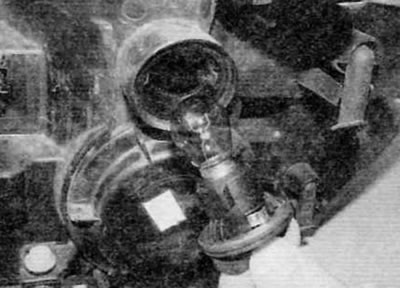
Figure 5.25, a. Turn the turn signal bulb socket counterclockwise to release it
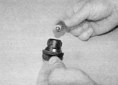
Figure 5.25, b. The lamp has a bayonet connection with the socket (late models)
26. Installation is carried out in the reverse order of removal.
Side turn signal repeaters
27. Push the light forward to release the rear clip, then release it from the front fender (figure 5.27).
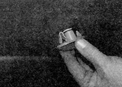
Figure 5.27. Press the side turn signal repeater forward and then release it from the fender
28. Turn the bulb holder counterclockwise and release it from the rear of the light. The lamp fits snugly into the lamp socket (figure 5.28, a, b).
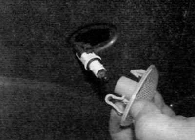
Figure 5.28, a. Turn the lamp holder counterclockwise to release it
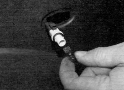
Figure 5.28, b. The lamp is installed in the socket with a tight fit
29. Installation is carried out in the reverse order of removal.
Fog lights
30. Remove the screws and partially remove the front wheel arch liner to gain access to the fog light.
31. Reach under the front bumper and disconnect the fog light electrical connector.
32. Turn the bulb holder a quarter turn and remove it from the flashlight.
33. Release the spring clip and remove the lamp from the socket.
34. When handling a new lamp, use a clean cloth to avoid touching the lamp bulb with your fingers. Moisture and oil present on human skin can cause this type of lamp to turn black and burn out quickly. If you do accidentally touch the lamp, wipe it clean with a clean cloth soaked in denatured alcohol.
35. Install the new lamp, ensuring that its mounting tabs are correctly positioned. Secure the lamp with the clamp and install the socket.
36. Connect the electrical connector of the fog light and install the wheel arch liner.
Taillights assembly
37. Open the liftgate or the corresponding double-leaf door.
38. Unscrew the plastic nut securing the light to the body (figure 5.38).
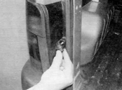
Figure 5.38. Unscrew the plastic nut securing the rear light to the body
39. Push the light towards the center of the car to release the two outer locking tabs and carefully pull it away from the body (figure 5.39, a, b).
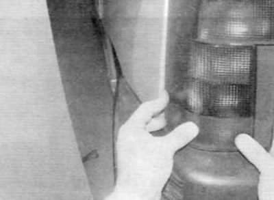
Figure 5.39, a. Push the light towards the center of the car...
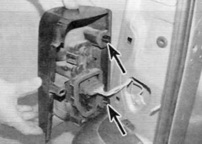
Figure 5.39, b....to release the two outer locking tabs (marked with arrows)
40. Press the tabs on the side of the bulb holder and remove the bulb holder from the flashlight (figure 5.40).
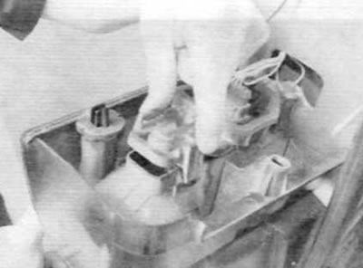
Figure 5.40. Press the tabs and remove the bulb holder from the flashlight...
41. All lamps have a bayonet connection. The corresponding lamp can be removed by pressing it and turning it counterclockwise (figure 5.41).
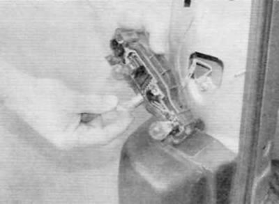
Figure 5.41. All lamps have a bayonet connection with the socket
42. Installation is carried out in the reverse order of removal. Make sure the headlight and bulb socket seals are in good condition.
High-mounted brake light
Models with lifting tailgate
43. Open the tailgate and unscrew the two nuts securing the light.
44. Remove the light and then press the two tabs to release the bulb holder (figure 5.44, a, b).
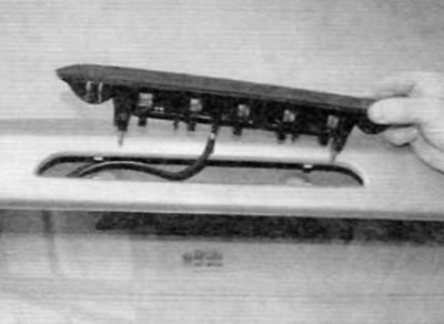
Figure 5.44, a. Remove the high brake light...
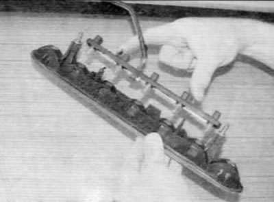
Figure 5.44, b....then press on the two tabs to release the lamp holder (models with a lifting tailgate)
45. All lamps are fixed in the holder with a tight fit (figure 5.45).
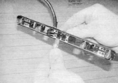
Figure 5.45. All lamps are fixed in the holder with a tight fit (models with a lifting tailgate)
46. Installation is performed in the reverse order of removal.
Models with a double-leaf tailgate
47. Open the corresponding rear door panel and carefully remove the inner brake light trim panel using a screwdriver (figure 5.47).
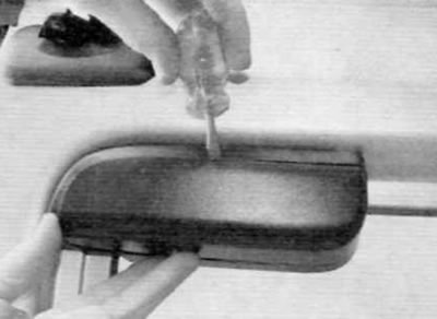
Figure 5.47. Remove the inner high brake light trim panel...
48. Press the two tabs to release the lamp holder (figure 5.48).
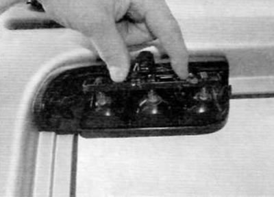
Figure 5.48. ...then press on the two tabs to release the lamp holder (models with a double-leaf tailgate)
49. All lamps are fixed in the holder with a tight fit (figure 5.49).
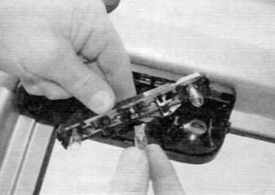
Figure 5.49. All lamps are installed in the lamp holder with a tight fit (models with a double-leaf tailgate)
50. Installation is carried out in the reverse order of removal.
License plate lights
Models with lifting tailgate
51. There is very little space between the license plate light and the plastic outer molding located above to remove the license plate lens. It is highly recommended to first remove the tailgate trim panel (see chapter 11). Then unscrew the three nuts and remove the outer molding (figure 5.51). The nuts can be accessed through holes on the inside of the tailgate.
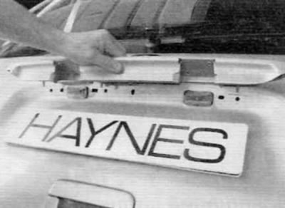
Figure 5.51. Remove the outer molding above the license plate light (models with a lifting tailgate)
52. Remove the lens from the license plate light. The lamp is inserted into the socket with a tight fit (figure 5.52, a, b).
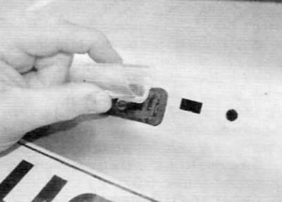
Figure 5.52, a. Remove the lens from the license plate light
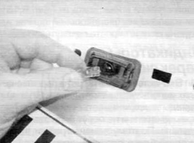
Figure 5.52, b. The lamp is installed in the socket with a tight fit (models with a lifting tailgate)
53. Fix the diffuser and install the outer molding.
54. Install the tailgate trim panel (see chapter 11).
Models with a double-leaf tailgate
55. Between the license plate light and the plastic outer molding. located above, there is very little space to remove the headlight diffuser. It is highly recommended to first remove the tailgate trim panel (see chapter 11), then proceed as described below.
56. Disconnect the electrical connector of the license plate light through the opening in the rear door (figure 5.56).
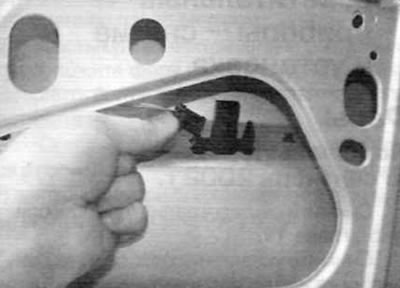
Figure 5.56. Disconnect the license plate light electrical connector (models with a double-leaf tailgate)
57. Press on the tabs and push the lantern out of the door (figure 5.57).
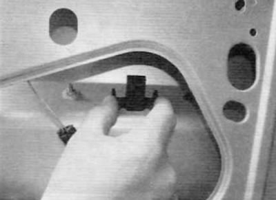
Figure 5.57, a. Press on the tabs.
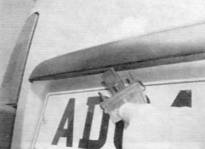
Figure 5.57, b....and push the lantern out of the door (models with a double-leaf tailgate)
58. Remove the lens from the license plate light (figure 5.58). The lamp is inserted into the socket with a tight fit.
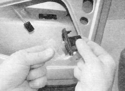
Figure 5.58. Disconnect the lens from the license plate light. The lamp is installed in the socket with a tight fit (models with a double-leaf tailgate)
59. Fix the diffuser and then install the lantern on the door. Connect the electrical connector and install the door trim panel (see chapter 11).