



Table of contents: Driver's airbag - removal 🠇 Driver's airbag installation 🠇 Passenger airbag removal 🠇 Passenger airbag installation 🠇 Side airbag 🠇 Upper side airbag 🠇 Coil spring - removal 🠇 Coil spring - installation 🠇 Airbag control unit 🠇
Caution: Before performing the following steps, please read the safety precautions described in paragraph 20.
Driver's airbag - removal
Models produced before September 2002.
1. Disable the airbag system as described in paragraph 20.
2. If necessary, turn the steering wheel to access the two airbag mounting screws. The screws are located on the rear of the steering wheel hub.
3. Remove the two screws securing the airbag module.
4. Carefully pull the airbag module out from the center of the steering wheel.
5. Carefully release the electrical connector from the clip on the airbag (work only with your fingers) and disconnect the connector by pulling the plug up away from the airbag.
6. If the airbag is to be stored removed from the vehicle for any period of time, refer to the storage precautions described in paragraph 20.
Models produced after September 2002.
7. Disable the airbag system as described in paragraph 20.
8. Insert a screwdriver into the three holes on the back of the steering wheel, one at a time, and push the inner retaining spring to the side to release the airbag retaining tabs. At the same time, pull the airbag away from the steering wheel to release it (figure 21.8, a, b).
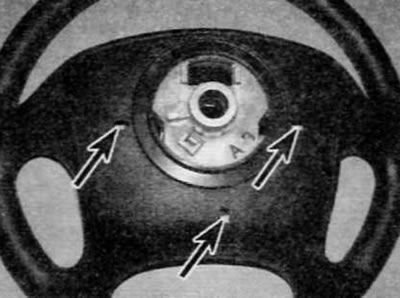
Figure 21.8, a. Insert the screwdriver into the three holes one by one (marked with arrows) on the back of the steering wheel...
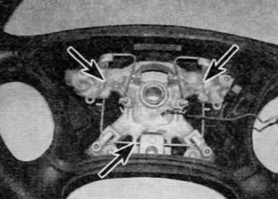
Figure 21.8, b....and move the internal locking spring away (marked with arrows) to the side to release the airbag tabs (shown with the airbag removed)
9. Disconnect the horn ground electrical connector, then release the retaining clip and disconnect the airbag electrical connector (figure 21.9, a, b). Remove the airbag module.
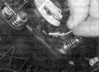
Figure 21.9, a. Disconnect the horn ground electrical connector...
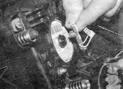
Figure 21.9, b....then release the retaining clip and disconnect the airbag electrical connector
10. If the airbag is to be stored removed from the vehicle for any period of time, refer to the storage precautions described in paragraph 20.
Driver's airbag installation
11. Installation is carried out in the reverse order of removal, taking into account the following points:
- a) Do not strike or drop the air bag module during installation.
- b) Securely connect the electrical connectors, then place the airbag unit into the steering wheel, being careful not to pinch the electrical wiring.
- c) If the airbag is secured with screws, tighten the screws securely.
- d) If the airbag is secured with a spring, push it into place until the clips are fully engaged.
- d) Once installation is complete, activate the airbag system as described in paragraph 20.
Passenger airbag removal
Models produced before September 2002.
12. Disable the airbag system as described in paragraph 20.
13. Remove the glove compartment.
14. Working through the storage compartment opening, remove the five airbag mounting bolts located at the base of the airbag module.
15. Release the retaining clip, disconnect the airbag electrical connector, and then remove the airbag module from the faceplate.
16. If the airbag is to be stored removed from the vehicle for any period of time, refer to the storage precautions described in paragraph 20.
Models produced after September 2002.
17. Disable the airbag system as described in paragraph 20.
18. Remove the front panel assembly as described in chapter 11.
19. Remove the air duct located above the airbag module.
20. Remove the four nuts securing the airbag module. Disconnect the airbag cover clips around the periphery of the cover and remove the airbag.
21. Release the retaining clip, disconnect the airbag electrical connector, and then remove the airbag module from the vehicle.
22. If the airbag is to be stored removed from the vehicle for any period of time, refer to the storage precautions described in paragraph 20.
Passenger airbag installation
23. Installation is carried out in the reverse order of removal, taking into account the following points:
- a) Do not strike or drop the air bag module during installation.
- b) Securely connect the electrical connectors, then place the airbag unit in its designated location, being careful not to pinch the electrical wiring.
- c) Tighten the airbag mounting screws/nuts securely.
- d) Install the front panel or storage compartment (whichever is applicable), as described in chapter 11.
- d) Once installation is complete, activate the airbag system as described in paragraph 20.
Side airbag
24. Removal and installation of the side airbag should be entrusted to a Peugeot/Citroen dealer. The seat must be disassembled to remove/install the airbag module.
Upper side airbag
25. Removal and installation of the upper side airbag should be entrusted to a Peugeot/Citroen dealer. To remove/install the airbag module, it is necessary to partially remove the headliner.
Coil spring - removal
Models produced before September 2002.
26. Remove the airbag module as described earlier in this paragraph.
27. Remove the steering wheel as described in chapter 10.
28. Remove the lower and upper steering column covers as described in chapter 11.
29. Trace the electrical wiring from the rotary electrical contact back to the electrical connector below the steering column and disconnect the electrical connector.
30. Remove the three screws and the coil spring from the steering column, passing the wiring harness through the shift lever bracket. Note the wiring harness layout.
Models produced after September 2002.
31. The airbag coil spring is an integral part of the steering column switch assembly located below the steering wheel. For detailed information on removal and installation, please refer to paragraph 4.
Coil spring - installation
32. Installation is carried out in the reverse order of removal, taking into account the following points for models produced before September 2002:
- a) Before installation, center the coil spring by aligning the marks on its body and the rotating central part. Instructions for centering the block are also provided on the label located on the surface of the block.
- b) Before installing the coil spring and steering wheel, make sure the wheels are in the straight ahead position.
- c) Before installing the steering column covers, route the coil spring wiring harness properly as noted before removal.
- d) Install the steering wheel as described in chapter 10, and install the airbag module as described earlier in this paragraph.
Airbag control unit
Removal
33. Disable the airbag system as described in paragraph 20.
34. Remove the center console as described in chapter 11, and then release the clamp and disconnect the airbag control unit electrical connector (figure 21.34).
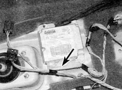
Figure 21.34. Release the clamp and disconnect the electrical connector (marked with an arrow) on the airbag control unit
35. Remove the bolts and then remove the control unit from the vehicle.
Installation
36. Installation is carried out in the reverse order of removal, taking into account the following points:
Source of the article is website: peugeotbook.ru
- a) Make sure that the arrow on the top surface of the block faces the front of the vehicle.
- b) Install the control unit mounting bolts and tighten them securely.
- c) Install the center console as described in chapter 11.
- d) Once installation is complete, activate the airbag system as described in paragraph 20.