



General information
1. Multifunctional electronic unit BSI (abbreviation of the term "Built-in Systems Interface" literally translated as "Embedded Systems Interface") is an electronic control unit that manages a number of functions normally controlled by separate control units and relays (for more information, see paragraph 1). The BSI unit is located on the left side of the front panel, directly below the fuse box. The BSI unit controls the following functions (not all features are available on all models):
- a) direction indicators/hazard warning lights;
- b) electric motors of the windshield/tailgate cleaner;
- c) rear window heating element;
- d) immobilizer;
- d) anti-theft alarm system;
- e) audible warning signal about the lights being on/the key being in the ignition switch;
- g) central locking/double locking system, including a remote control receiver for central locking;
- c) open door warning indicator;
- i) interior lighting turn-off delay timer.
2. If a malfunction occurs in any of the above functions, first check the condition of the fuses. If this does not solve the problem, have the vehicle checked by a Peugeot/Citroen dealer.
Removal
3. Disconnect the ground wire from the battery (see "Disconnecting the battery").
4. Remove the lower section of the front panel on the driver's side (turn the fasteners 90° and remove the panel).
5. On early models, remove the screw (if applicable), release the clamp and rotate the E3SI unit downwards to disconnect it from the base of the fuse box (figure 22.5).
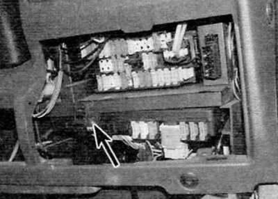
Figure 22.5. On early models, remove the screw (marked with an arrow), then release the clamp and rotate the BSI unit downwards
6. On later models, turn the two white plastic tabs 90 degrees counterclockwise and gently pull the fuse box out. Lower the back edge of the block, then lift the front edge and slide the block out.
7. On all models, disconnect all electrical connectors from the E3SI unit, but first mark their installation position and release the clamps. After this, remove the BSI unit from the vehicle. Please note that different electrical connectors may have different locking designs. Take the time to study the design of each specific connector so that you can disconnect it without applying excessive force, as the locking mechanism can be damaged quite easily.
Installation
8. Installation is carried out in the reverse order of removal. Connect all electrical connectors securely. Please note that the colours of the electrical connectors are listed next to the connector sockets on the BSI unit.