



Table of contents: Description and precautions 🠇 Electronic maintenance (contactless)…🠇 Removal and installation a…🠇 Contactless distributor -…🠇 Ducellier distributor 🠇 Bosch/Marelli distributor 🠇 Ignition timing adjustment 🠇 Removal and installation the…🠇 Remote controlled door locks 🠇 Troubleshooting 🠇
Description and precautions
1. The electronic ignition system installed on the latest models uses electrical impulses generated by the distributor for its operation. The pulses are generated by magnetic induction and are amplified by the ignition module, which supplies low voltage current to the coil. High voltage is generated and transmitted in a traditional way.
2. Electronic ignition systems are generally very reliable because they do not have a contact breaker, the wear of which over time leads to system failure.
3. Be careful not to damage the ignition module or distributor by applying current of the wrong polarity or too much voltage to them (for example, you cannot use a fast charger when the battery is connected). The electronic ignition system may contain very high voltages - be careful not to get an electric shock.
Electronic maintenance (contactless) ignition systems
4. Routine maintenance of the system consists of periodic cleaning and replacement of spark plugs. The high voltage wires, ignition coil and distributor cap should be cleaned and inspected at the same frequency. From time to time, you should inspect the distributor cap (from the inside) and the rotor for burns and cracks, and at the same time lubricate the centrifugal ignition regulator mechanism with light oil.
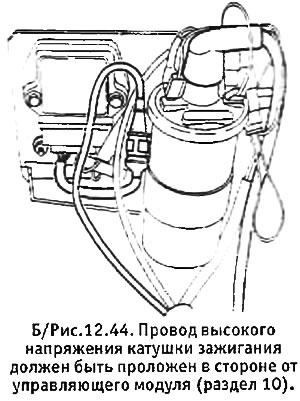
5. Check that the high voltage wire of the coil is routed away from the control module (see B/Figure 12.44). If this wire is too close to the module or ignition wires, it may cause misfiring and erratic movement of the tachometer needle.
Removal and installation a contactless distributor
6. Release the clamps and remove the distributor cap, bending back the protective rubber cover. Mark the relative position of the distributor mounting flange and the thermostat/fuel pump housing.
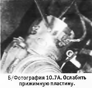
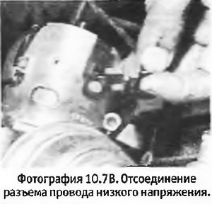
7. Loosen the pressure plate and disconnect the low voltage wire (see photos).
 |
 |
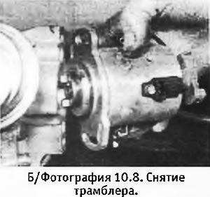
8. Unscrew the 2 mounting nuts and pull out the distributor (see photo).
9. The distributor is installed in reverse order. The distributor has an offset drive, so it is impossible to install it incorrectly. When installing a new distributor, align it in the middle of the stroke allowed by the slots in the drive.
10. Check and, if necessary, adjust the ignition timing.
Contactless distributor - disassembly and assembly
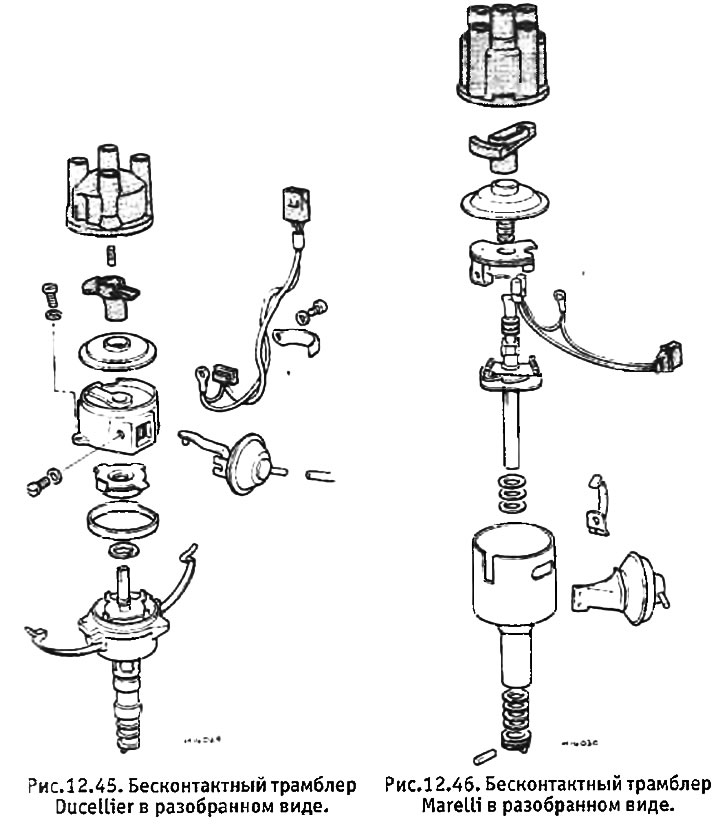
11. Before starting disassembly, check whether spare parts are available for sale. If the mechanical parts of the distributor wear out, the entire assembly will have to be replaced.
Ducellier distributor
12. Begin disassembly by removing the screws that hold the upper and lower halves of the distributor housing together. The mounting tabs are offset to ensure correct distributor assembly. Disconnect the halves of the body.
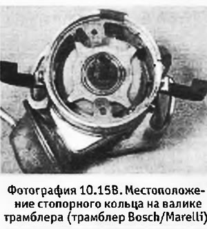
13. Remove the electromagnetic sensor coil and vacuum block from the upper half of the housing (pay attention to which hole the vacuum block rod is inserted into). Remove the retaining ring from the shaft, after which you can remove the rotor and weights of the centrifugal ignition regulator. The drive dog is attached to the shaft with a pin.
14. The distributor is assembled in reverse order.
Bosch/Marelli distributor
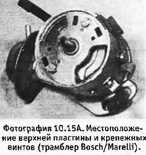
15. The disassembly procedure is similar to that just described, however the distributor housing is made of one piece (see photos). Remove the top plate and retaining ring from the shaft.
 |
 |
Ignition timing adjustment
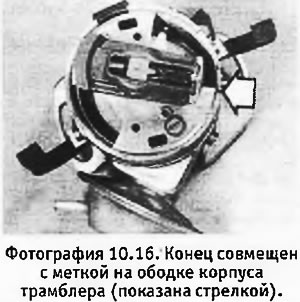
16. In case of an electronic system, static ignition control is not possible. On the rim of the distributor housing there is a mark corresponding to the position of the runner during ignition in cylinder No. 1. This mark can be used when adjusting the ignition timing "from zero".
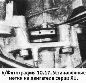
17. Dynamic adjustment is carried out using a stroboscope connected to ignition wire No. 1. On XU series engines, timing marks are applied to the rim and flywheel housing, and they are visible without any disassembly (see photo).
18. Disconnect and plug the vacuum tube and then check the ignition timing at idle speed.
Removal and installation the electronic ignition module
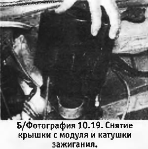
19. Remove the cover from the coil and module (see photo).
20. Disconnect the wiring harness from the module.
21. Unscrew the 2 mounting screws and remove the module from the support plate.
22. The module is installed in reverse order.
Remote controlled door locks
23. On the latest GTX models, the door locks are controlled remotely using a special controller, rather than from the ignition key.
Troubleshooting
24. If there are any system failures, check (using a stroboscope), is there high voltage on the wire connecting the coil to the distributor?. If there is voltage, then the fault lies in the high voltage distribution system (see section 14).
25. Check how the ignition coil high voltage wire is routed (see above).
26. If you have a multimeter, check the resistance of the windings of the pulse generator coil in the distributor and the ignition coil. (First, you need to turn off the ignition and disconnect the coil being tested). The required resistance values are indicated in Specifications.
27. Inspect the pulse generator coil for mechanical damage and check the gap between the rotor and stator, which should be the same for all 4 rotor poles. If mechanical damage is detected, the distributor must be replaced. (On distributors with an upper support plate, the rotor clearance can change after removing the plate).
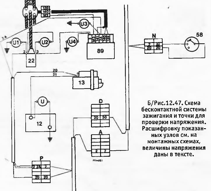
28. Using a multimeter or a low-watt 12 V light bulb, check the voltage at the points shown in B/Figure 12.47 with the ignition on.
You should get the following results:
- U (on the battery terminals) = minimum 11 V
- U1 (terminal + ignition coil) = battery voltage. If this is not the case, then the coil power supply wire is damaged
- U2 (at the low voltage terminals of the ignition coil) = 0 V. If there is voltage here, then either the module is faulty, or the wire connecting the coil to the module is damaged and has reached the ground
- U3 (terminal 15 of the module) = battery voltage. Zero voltage here indicates a break in the wire running from the connector to the module
- U4 (terminal 16 of the module) = battery voltage. Zero voltage here indicates an open in the wire running from the ignition coil to the module.
29. Further diagnostics of the system should be performed by a specialist.