



As for the diesel engine, it does not need the ignition system required by gasoline engines. Diesel engines have a strong compression of the incoming air, accompanied by a significant increase in temperature. When fuel is injected into the compressed and heated air, it self-ignites.
Depending on the configuration, the ignition system of the vehicles in question can be static - without an ignition distributor, the terminals of the ignition coil are directly connected to the high-voltage wires of the spark plugs. An ignition system without a distributor means that the secondary winding of the ignition coil generates the high-voltage current required for a spark discharge. This voltage is supplied from the coils to the spark plugs via the high-voltage wires through the distributor.
All engines with a fuel injection system are equipped with an ignition system controlled by the same electronic unit as the fuel injection system.
The electronic control unit has a multi-pin plug connector, which allows it to supply power to the injection and ignition system components, as well as receive information from the elements of these systems (see illustrations 1.0 and 1.0a).
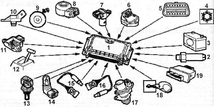
1.0 Input signals to the electronic control unit of the injection and ignition systems
1 - injection and ignition system control unit
2 - hydraulic fluid pressure sensor
3 - battery
4 - refrigerant pressure sensor (if provided)
5 - diagnostic connector
6 - accelerator pedal position sensor
7 - crankshaft position sensor
8 - knock sensor
9 - speedometer sensor
10 - intake manifold air pressure sensor
11 - throttle position potentiometer
12 - Automatic transmission control unit (depending on the configuration)
13 - coolant temperature sensor
14 - intake air temperature sensor
15 - lambda probe (oxygen sensor)
16 - lambda probe (oxygen sensor)
17 - Input shaft speed sensor
18 - immobilizer
19 - Engine control unit relay
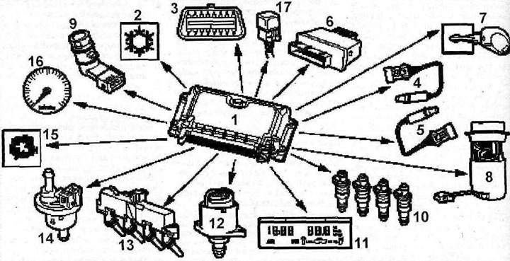
1.0a Actuators of injection and ignition systems
1 - injection and ignition system control unit
2 - refrigerant pressure sensor
3 - diagnostic connector
4 - lambda probe (oxygen sensor)
5 - lambda probe (oxygen sensor)
6 - Engine control unit relay
7 - immobilizer
8 - fuel pump
9 - throttle valve heater
10 - fuel injectors
11 - on-board computer
12 - stepper motor of idle speed controller
13 - ignition coil block
14 - Evaporative Emissions Blow-off Solenoid Valve
15 - Engine status indicator light
16 - tachometer
17 - turbocharger relay (if provided)
The ignition coils are designed as a contact block mounted on the cylinder head.
The memory of the injection and ignition system control unit contains parametric data determined during bench and road engine tests. The control unit gives a command to the ignition coils by sending the corresponding pulses from the crankshaft position sensor, which reads the crankshaft revolutions. In addition, the control unit receives information from the coolant temperature and intake air temperature sensors, as well as the throttle valve angular displacement potentiometer.
The throttle potentiometer informs the electronic control unit about the position of the throttle valve, which can close the inlet, open it partially or completely. Based on the information received, the electronic control unit determines the acceleration and increase in speed, braking or forced idle mode.
The electronic control unit calculates the ignition advance angle, sets the ignition coil charging duration in accordance with the engine speed, determines the battery voltage and the voltage on both coil windings.
Attention! The probability of damaging expensive system components when performing repair and adjustment work on your own is very high, so we recommend entrusting all work related to the ignition system to a specialized workshop.
To avoid high voltage electric shock when performing work, the following rules must be observed:
- a) persons with a pacemaker are not allowed to work with electronic ignition systems;
- b) Do not touch or disconnect the ignition system wires, and do not crank the engine with the starter while the engine is running;
- c) work on the system is permitted only with the engine turned off and the ignition switched off;
- d) connection and removal of control and measuring instruments is permitted only with the engine turned off and the ignition switched off;
- d) connection of control lamps to the terminals of the ignition coil is not permitted;
- e) Do not turn the engine with the starter unless all ignition system components are installed;
- g) Do not perform measurements with the engine running or with the engine cranked using the starter if this requires connecting one of the wires to the "ground" (-);
- c) Do not allow high voltage wires to be connected to ground (-).
Defective ignition system components can cause engine malfunctions.
If the engine is running poorly, the cause may be a faulty crankshaft position sensor, ignition coil or control unit.
If the engine does not work at all, but the main functions of the ignition system are in order, then the cause of the engine failure may be a failure of the automatic adjustment of the ignition advance angle. Such a failure can only be identified and eliminated by a workshop, because in this case, control and measuring devices are needed, with the help of which a corresponding diagram is drawn up, allowing you to quickly detect an error in the settings.
In general, the ignition system is designed for a long service life and does not require maintenance. It is only necessary to change the spark plugs regularly.