
English Русский
Български
Беларускі
Український
Српски
Hrvatski
Română
Polski
Slovenský
Magyar
Bookmark Articles Sitemap Contacts
Company Hyundai Company Opel Company Skoda Company Kia Company Mitsubishi Company LADA Company Audi
PeugeotBook.ru


Series 100   Series 200   Series 300   400-500   Series 600   Crossovers   Others
 
Partner I (1996-2008) Peugeot 807 (2002-2014) Peugeot 806 (1994-2002) Peugeot J5 (1981-1993)

Fuel Rail (2.0L Engine Models) — removal and installation (Peugeot Partner I)

  • Main
  • Пежо
  • Partner I (1996-2008)
  • Power unit
  • Power and exhaust (DW diesels)
  • Fuel Rail (2.0L Engine Models) — removal and installation
0
Table of contents: Removal 🠇 Installation 🠇
Caution: Before starting work, please refer to the safety precautions described in paragraph 2.


Note: Installation will require a complete new set of high pressure fuel lines.


Removal


1. Disconnect the ground cable from the battery (see "Disconnecting the battery").

2. Unscrew the four plastic nuts and remove the engine cover (figure 3.20, a.b).

3. Disconnect the electrical connectors at the fuel injectors and at the piston shut-off device on top of the fuel pump.

4. Unscrew the two nuts securing the plastic guide of the electrical wiring harness to the cylinder head. Remove the guide from the two support studs and slide it towards the fuel rail. If necessary, disconnect the appropriate electrical connectors so that the wiring harness assembly can be moved away from the guide for further ease of access.

5. Loosen the clamp and disconnect the crankcase ventilation hose from the cylinder head cover.

6. Disconnect the quick release couplings of the fuel supply and return hoses at the top of the fuel pump: use a small screwdriver to release the retaining clip. Seal open connections appropriately to prevent dirt from entering.

7. Similarly, disconnect the quick-release couplings of the supply and return fuel hoses on the fuel filter and plug the open connections. Release the fuel hoses (and on later models, a booster pump) from the corresponding clamps.

8. Thoroughly clean the high-pressure fuel line fittings on the fuel rail, fuel pump and injectors. Using an open-end wrench, loosen the union nuts securing the high-pressure fuel lines to the fuel pump and fuel rail. When loosening the union nuts, hold the fittings on the pump and fuel rail with a second wrench. Remove the high pressure fuel line and plug any open connections to prevent dirt from entering.


9. Again using two wrenches, hold the fittings and unscrew the union nuts securing the high-pressure fuel lines to the fuel injectors and fuel rail. Remove high pressure fuel lines and plug open connections to prevent dirt ingress (figure 16.9, a, b).
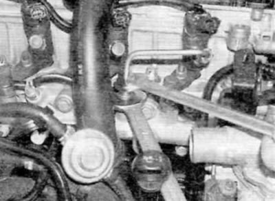
Figure 16.9, a. Hold the fittings while loosening the union nuts on the high-pressure fuel lines…

Figure 16.9, a. Hold the fittings while loosening the union nuts on the high-pressure fuel lines connecting the pump and injectors to the fuel rail, then remove the fuel lines and discard them (models with a 2.0 L engine)
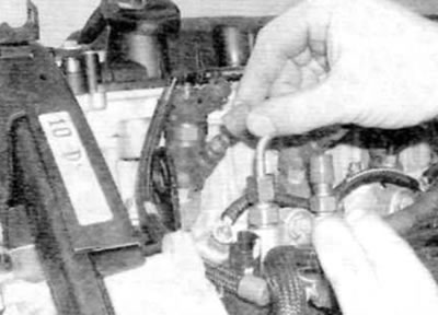

Figure 16.9, b. Plug all connections to prevent dirt from entering the fuel system (models with a…

Figure 16.9, b. Plug all connections to prevent dirt from entering the fuel system (models with a 2.0 L engine)


10. Disconnect the electrical connectors of the fuel temperature sensor and the fuel pressure sensor on the fuel rail.


11. Unscrew the three bolts securing the fuel rail to the cylinder head and remove the guide from its standard location (figure 16.11, a, b).
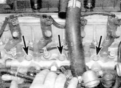
Figure 16.11, a. Remove the bolts (marked with arrows)...
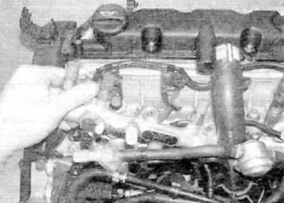
Figure 16.11, a. Remove the bolts (marked with arrows)...


Figure 16.11, b....and move the fuel rail out of its standard position (models with a 2.0 L engine)

Figure 16.11, b....and move the fuel rail out of its standard position (models with a 2.0 L engine)


Warning. Do not attempt to remove the four male high pressure fuel line fittings from the fuel rail. These components are not supplied separately and if they are disconnected during assembly, fuel may leak.


12. Before installation, purchase a new set of high pressure fuel lines.

Installation


13. Install the fuel rail in place, screw in the three bolts and tighten them to the specified torque.

14. Working with one fuel injector at a time, remove the plugs from the fittings on the fuel rail and the corresponding injector. Connect the new high pressure fuel line to the fittings and at this stage tighten the union nuts using hand force only.


15. After preliminary connecting all four fuel lines, hold the fittings with a wrench and, using a torque wrench and the appropriate adapter, tighten the union nuts to the specified torque (figure 16.15).
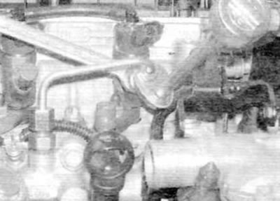
Figure 16.15. Using a torque wrench and a special adapter, tighten the union nuts of the fuel lines…

Figure 16.15. Using a torque wrench and a special adapter, tighten the union nuts of the fuel lines (models with a 2.0 L engine)


16. Similarly, connect the new high-pressure fuel line to the fuel pump and fuel rail and tighten the union nuts to the specified torque.

17. Connect the electrical connectors of the fuel temperature sensor and the fuel pressure sensor.

18. Remove the plugs and connect the quick-release couplings of the feed and return hoses on the fuel filter and the connections at the top of the fuel pump. Secure the hoses with appropriate clamps.

19. Connect the crankcase ventilation hose to the cylinder head cover.

20. Install the plastic wiring harness guide onto the two support studs and secure with nuts.

21. Reconnect the electrical connectors for the fuel injectors and the pump piston cut-off switch and reconnect all other wiring that was disconnected for access.

22. Make sure all connectors are connected and all wiring is secured with the appropriate clamps, then connect the ground cable to the battery.


23. Observing the precautions described in paragraph 2, fill the fuel system as described in paragraph 6. Then start the engine and let it idle. Check high pressure fuel line connections for leaks while the engine is idling. If everything is OK, increase the engine speed to 4000 rpm and check for leaks again. Take the vehicle for a short road test and check for leaks again upon return. If leaks are detected, purchase and install new high-pressure fuel lines. Do not attempt to fix even the smallest leak by tightening the fuel line fittings.

24. Finally, install the engine cover.
This article is available at russian, bulgarian, belarusian, ukrainian, serbian, croatian, romanian, polish, slovak, hungarian
Article reviewed by editor: Nikonova Veronica
Share information:
Previous
Partner I: Power and exhaust (DW diesels)
Next

Fuel injectors — removal and installation
Fuel injection advance — checking and adjustment
High-pressure fuel pump — removal and installation
Electrical components of the fuel injection system — removal and…
High-pressure fuel pump (models with 1.9L engine) — adjustment
Intake manifold — removal and installation
Exhaust manifold — removal and installation
Turbocharger (2.0L Engine Models) — design description and…
Turbocharger (2.0L engine models) — removal, inspection and…
Exhaust system — general information, removal and installation
See similar information for other Peugeot models

➨ Fuel filter renewal — carburetor models Peugeot 106 (1991-2003)
➨ Cleaning the fittings on the high-pressure fuel rail Peugeot 207 (2006-2014)
➨ Range of engine models Peugeot 306 (1993-2002)
➨ Dehydration of diesel engine fuel filter (7500 km) Peugeot 405 (1987-1997)
➨ Precautions when working on the fuel system of a diesel engine Peugeot 605 (1989-2000)
Link to this article in different formats
Comments and feedback from visitors
No comments yet


Add two numbers 44 + 25


Partner I (1996-2008) 
  • General information
  • Introduction to the guide
  • Faults en route
  • Weekly checks
  • User manual
  • Maintenance (petrol)
  • Maintenance (diesel)
  • Power unit
  • Petrol engines
  • Diesel engines «XUD»
  • Diesel engines «DW»
  • Overhaul of petrol engines
  • Overhaul of diesel engines
  • Cooling and heating
  • Power and exhaust (petrol)
  • Power and exhaust (XUD diesels)
  • Power and exhaust (DW diesels)
  • Emission reduction
  • Starting and charging system
  • Transmission
  • Clutch
  • Mechanical gearbox
  • Drive shafts
  • Chassis, running gear
  • Brake system
  • Car suspension
  • Steering
  • Body and interior
  • Exterior (external elements)
  • Interior (internal elements)
  • Doors, locks and windows
  • Electrical equipment
  • Equipment and devices
  • Electrical circuits
Peugeot 807 (2002-2014) 
  • General information
  • Operating instructions
  • Maintenance
  • Troubleshooting
  • Power unit
  • Gasoline engines
  • Diesel engines
  • Cooling and heating
  • Fuel injection (petrol)
  • Fuel system (diesel)
  • Fuel system
  • Exhaust system
  • Ignition system
  • Transmission
  • Clutch
  • Manual gearbox
  • Automatic gearbox
  • Chassis, running gear
  • Brake system
  • Car suspension
  • Steering system
  • Body and interior
  • Exterior (external elements)
  • Interior (internal elements)
  • Electrical equipment
  • Power devices
  • Electrical circuits
Peugeot 806 (1994-2002) 
  • General information
  • User manual
  • Maintenance
  • Power unit
  • Petrol engines
  • Diesel engines
  • Lubrication system
  • Cooling system
  • Fuel injection (petrol)
  • Fuel system (diesel)
  • Ignition and exhaust systems
  • ECM Bosch Motronic MP 3.2
  • ECM Magneti-Marelli (MM)
  • Transmission
  • Clutch
  • Mechanical gearbox
  • Chassis, running gear
  • Brake system
  • Car suspension
  • Steering
  • Electrical equipment
  • Equipment and devices
  • Electrical circuits
Peugeot J5 (1981-1993) 
  • General information
  • Introduction to manual
  • Specifications
  • Gasoline engine
  • Engine repair
  • Lubrication system
  • Cooling system
  • Fuel system
  • Ignition system
  • Diesel engine
  • Engine repair (DB9)
  • Lubrication system (DB9)
  • Cooling system (DB9)
  • Fuel injection (DB9)
  • Engine repair (U25)
  • Lubrication system (U25)
  • Cooling system (U25)
  • Fuel injection (U25)
  • Transmission
  • Clutch
  • Gearbox
  • Drive shafts
  • Chassis, running gear
  • Steering system
  • Car suspension
  • Brake system
  • Electrical equipment
  • Power devices
  • Electrical circuits
PeugeotBook.ru © 2018–2026 | Mobile version | Sitemap: EN BG BY UA RS HR RO PL SK HU | Write message | Site search | Add to bookmarks | Peugeot owners
106 (1991-2003) | 206 (1998-2012) | 207 (2006-2014) | 305 (1977-1989) | 306 (1993-2002) | 307 (2001-2008) | 405 (1987-1997) | 406 (1995-2004) | 605 (1989-2000) | Partner-I (1996-2008) | Eurovans-807 (2002-2014) | Eurovans-806 (1994-2002) | J5 (1981-1993) |
Cookies are used to ensure the correct display of pages on the site.