
Attention! Take special precautions when working on fuel injectors. Never expose your hands or any other part of your body to the jet of fuel from the injector, as the high operating pressure can cause fuel to penetrate the skin, potentially resulting in death. It is highly recommended that you have your dealer or diesel fuel system technician check the pressurized injectors.
Models with 1.9L engine
Warning. Be careful not to allow dirt to enter the high pressure fuel pump or injectors during this procedure.
Removing
1. Remove the upper section of the intake manifold as described in paragraph 17.
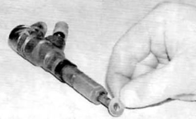
2. Disconnect the return line (-s) from the nozzle to be removed (pic. 15.2).
Pic. 15.2. Disconnecting the fuel return line from the injector (models with 1.9 l engine)
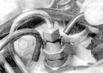
3. Thoroughly remove dirt from all injector line fittings. Loosen the union nuts securing the injector fuel lines to the high pressure fuel pump and injectors (pic. 15.3).
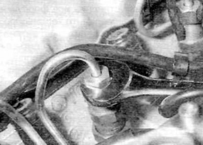
Fig.15.3 Unscrewing the union nut on the nozzle (models with 1.9 l engine)
Hold the fittings on the pump while unscrewing the union nuts securing the pipelines to the pump. Remove the fuel lines as a set. Plug the fittings on the high pressure fuel pump/injectors to prevent dirt from entering.
4. On WJY engines, if the No. 1 injector is being removed, trace the needle lift sensor wiring from the injector and disconnect the appropriate electrical connector on the main wiring harness.
5. Remove all traces of dirt from the area around the injector, and then unscrew the injector from the cylinder head. Remove the injector flame deflector from the cylinder head and discard; when installing, use a new one.
Warning. Do not drop the nozzles and be careful not to damage the nozzle tips. The nozzles are manufactured to very precise tolerances and must be handled with care. For example, never clamp them in a vise.
Installation
6. Install the new flame deflector with its convex surface facing up (to nozzle).
7. Carefully install the nozzle on the cylinder head and tighten it to the prescribed torque.
8. Connect the return line (-s) to the nozzle. Connect the needle lift sensor electrical connector if necessary.
9. With all injectors correctly installed, install and connect the injector fuel lines. Pre-tighten all union nuts to ensure that all fuel lines are correctly positioned, then tighten them to the specified torque in the same sequence. Hold the fittings on the high pressure fuel pump while tightening the nuts on the pump side. Install and connect fuel injector lines.
10. Install the intake manifold as described in paragraph 17.
11. Fill the fuel system as described in paragraph 6. Before installing the engine cover, start the engine and check for signs of fuel leaks.
Models with 2.0L engine
Attention! Before starting work, please refer to the precautions described in paragraph 2.
Note. The following procedure describes the removal and installation of the injectors as a single set, although each injector can be removed individually if required. Each damaged injector will require new copper washers, top seals, injector clamp nuts, and high pressure fuel lines during installation.
Removing
12. Follow the steps in p.p. 1-4 paragraph 16.
13. Disconnect the fuel supply and return hose quick couplings at the top of the fuel pump, while using a screwdriver to release the locking clip. Seal open connections appropriately to prevent dirt from entering, then free fuel hoses (and on later models, a booster pump) from the corresponding clamps.
14. Thoroughly clean all high pressure fuel line fittings at fuel injectors and fuel rail. Using two open end wrenches, remove the union nuts securing the high pressure fuel lines to the fuel injectors and fuel rail (pic. 15.14). Remove high pressure fuel lines and plug open connections at injectors and fuel rail to prevent dirt from entering. Be aware that installation will require a new high pressure fuel line for each removed injector.
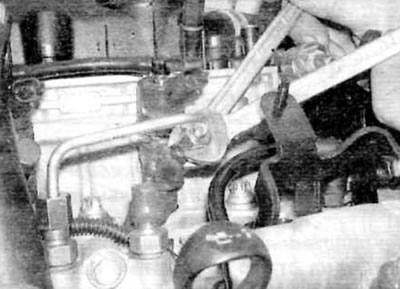
Pic. 15.14. Hold the adapters while releasing the union nuts, then remove and discard the high pressure fuel line from the injector to the fuel rail (models with 2.0 l engine)
15. Remove retaining ring and disconnect return line from each fuel injector (pic. 15.15).
Pic. 15.15. Remove the clamp and disconnect the fuel return line fitting from the injector (models with 2.0 l engine)
16. Remove the nut and washer securing each injector clamp to its stud on the cylinder head (pic. 15.16). Keep in mind that new clamp nuts will be required during installation.
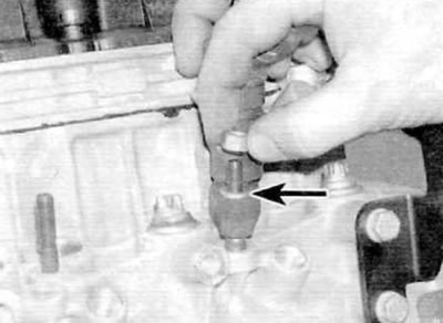
Pic. 15.16. Loosen the injector mounting nut and remove the washer (marked with an arrow) (models with 2.0 l engine)
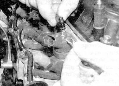
17. Remove the injectors along with their clips from the cylinder head (pic. 15.17). Remove the clamp from the nozzle after releasing it from the support pin. If the injectors are tight «sitting» in the cylinder head and cannot be released, unscrew the support pin with a pin remover and slide out the injector clamp. By inserting an open end wrench into the mounting section on the nozzle body, release the nozzle by turning it while pulling it up.
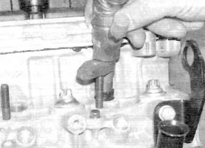
Pic. 15.17. Remove the nozzle and clip from the cylinder head (models with 2.0 l engine)
18. Remove the injector clamp locating pin from the cylinder head (pic. 15.18).
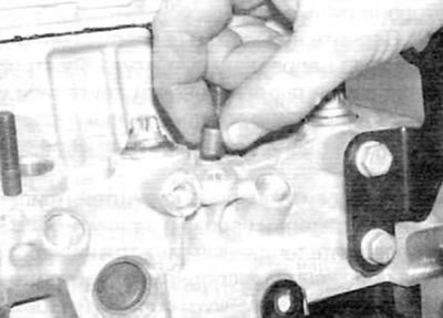
Pic. 15.18. Remove the injector clamp locating pin (models with 2.0 l engine)
19. Remove the copper washer and top seal from each injector or remove from the mounting hole in the cylinder head. if they were left there when the injector was removed. Installation will require new copper washers and top seals.
20. Visually inspect each nozzle for obvious signs of damage or deterioration. If there are obvious defects, replace the nozzle (-And).
Warning. Fuel injectors are manufactured to very tight tolerances and should never be disassembled. Do not unscrew the fuel line fitting on the side of the injector or disconnect any items from the injector body. Do not attempt to remove carbon deposits from the nozzle atomizer or perform any ultrasonic or pressure test.
21. If the injectors are in satisfactory condition, plug the fuel line fitting (if you haven't already) and plug the electrical connector and injector accordingly.
22. Before installing, purchase a new copper washer, top seal, injector clamp retaining nut, and high pressure fuel line for each removed injector.
Installation
23. Install a new top seal on each injector body and install a new copper washer on the injector (pic. 15.23, a, b).
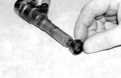
Pic. 15.23 a. Put the new top seal on the injector...
Pic. 15.23 b....then install a new copper washer (models with 2.0 l engine)
24. Establish adjusting pins of clips of atomizers on a head of cylinders.
25. Install the injector clip into the groove on each injector body and install the injectors into the cylinder head. Guide the clip over the support pin and dowel pin when installing each nozzle.
26. Install a washer and thread a new nozzle clamp nut onto each support stud. At this stage, tighten the nuts only by hand.
27. Working with one fuel injector at a time, remove the plugs from the fittings on the fuel rail and the corresponding injector. Connect the new high pressure fuel line to the fittings and screw on the union nuts. Be careful not to damage the threads on the nut or deform the fuel lines when installing them. After «bait» union nut, tighten it at this stage only with medium force.
28. After pre-connecting all fuel lines, tighten the injector clamp nuts to the prescribed torque.
29. Using a spanner wrench, hold the union of each fuel line in turn and tighten the union nut to the prescribed torque using a torque wrench and a special adapter. Tighten any disturbed union nuts in the same way.
30. Connect return lines to each fuel injector and secure with circlips.
31. Remove the plugs and connect the quick couplings for the supply and return hoses at the top of the fuel pump. Secure the hoses with appropriate clamps.
32. Install the plastic wire harness guide onto the two support studs and secure with nuts.
33. Connect the electrical connectors for the fuel injectors and pump piston shut-off switch and connect all other electrical wiring disconnected for access.
34. Make sure that all connectors are mated and all wiring is secured with the appropriate clamps, and then connect the wire «masses» to the battery.
35. By observing the precautions described in paragraph 2. fill the fuel system as described in paragraph 6. Then start the engine and allow it to idle. Check the high pressure fuel line connections for leaks with the engine idling. If everything is in order, increase the engine speed to 4000 rpm and check for leaks again. Carry out a short road test of the vehicle and check for leaks again upon return. If leaks are found, purchase and install new high pressure fuel lines. Do not attempt to repair even the smallest leak by further tightening the fuel line unions.
36. Finally, install the engine cover.