
Cars with manual transmission VEZ
1. Open the hood and lock it in this position.
2. Drain the coolant.
3. Remove the battery.
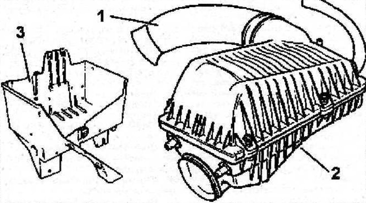
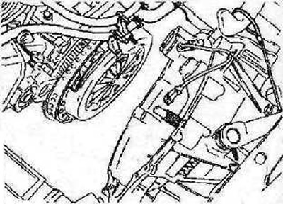
4. Disconnect the air intake 1 (see illustration).
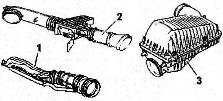
3.4 Disconnect air intake 1
5. Remove the supply air duct 2 with the mass air flow sensor (if provided) (see illustration 3.4).
6. Remove the air filter 3 (see illustration 3.4).
7. Remove the battery tray.
8. Disconnect the upper radiator hose.
9. Release from the holders and move away from the place of work all wires, plugs, pipelines and hoses connected to the gearbox.
10. Install the support beam on the front end «A», to raise the engine and relieve the load on the power block supports, or secure the gearbox to a cable «b», to lift it up with a crane (see illustration). If there is no crane to lift the gearbox, the box can be lifted by moving a garage lift under it. When installing the box on a lift, place it on wooden slats or bars to avoid damaging the crankcase.
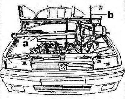
3.10 Install the support beam on the front end «A», to raise the engine and relieve the power block supports, or secure the gearbox to a cable «b», to lift it up with a crane
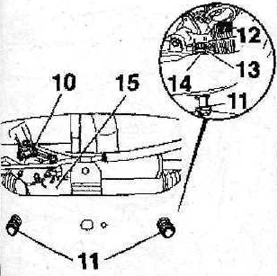
11. Remove bracket 4 transmission support (see illustration).
3.11 Remove bracket 4 transmission support
12. Remove and replace bushing 5 (see illustration).
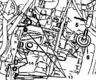
3.12 Remove and replace bushing 5
13. Move the starter away from the work site without disconnecting it.
14. Remove the speedometer shaft, washer 6 must be replaced (see illustration 3.12).
15. Unscrew the top bolts of fastening of a transmission to the engine.
16. Remove the crankshaft position sensor.
17. Remove the mudguard.
18. Drain gear oil.
19. Remove drive shafts (see illustration).
20. Remove the cover 8 of the output shaft (see illustration).
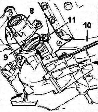
3.20 Remove the cover 8 of the output shaft
21. Remove the O-ring 9, remove the clutch cover 10, and then unscrew the lower bolt 11 of the gearbox to the cylinder block (see illustration 3.20). The tightening torque for bolt 11 is 50 Nm.
22. Raise the engine to relieve the power block supports (see illustration 3.10).
23. Separate the engine from the gearbox and move the gearbox away from the engine as far as possible (see illustration).
3.23 Disengage the engine from the gearbox and move the gearbox as far back as possible
24. Lock the flywheel by installing the stop FACOM D86 in the appropriate hole.
25. Remove pressure and driven clutch discs.
26. Remove the flywheel.
27. Cover the radiator with cardboard to prevent damage.
28. Make sure the gearbox is securely attached to the lift (depending on which device - garage lift or crane - is used for dismantling), and carefully remove the box from under the vehicle.
Vehicles with manual transmission ML5T
29. Disconnect the wires from the battery and remove it.
30. Remove the air filter.
31. Remove the battery tray.
32. Disconnect the clutch slave cylinder 1 by first pressing on it (see arrow 2 in illustration), and then turning it counterclockwise (see arrow 3 in the illustration).
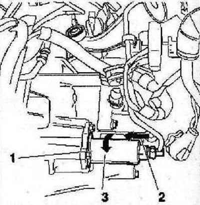
3.32 Disconnect the slave cylinder 1 of the clutch by first pressing on it (see arrow 2), and then turning it counterclockwise (see arrow 3)
Attention! Do not depress the clutch pedal with the clutch slave cylinder removed.
33. Remove clamps 4 and 5, then disconnect the cable tie rod ends from the spherical heads 6 and 7 of the select and shift rods using 0216-G1 10 mm and 0216-G2 13 mm pullers (see illustration).
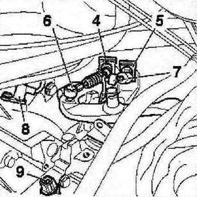
3.33 Remove clamps 4 and 5, then disconnect the cable tie rod ends from the spherical heads 6 and 7 of the selection and shift rods using pullers
34. Remove the sensor 8 the number of revolutions of the crankshaft (see illustration 3.33).
35. Disconnect the switch plug 9 reversing lights (see illustration 3.33).
36. Disconnect the speedometer sensor.
37. Disconnect, release from the holders and move away from the place of work all harnesses connected to the gearbox.
38. Loosen wheel hub nuts.
39. Unscrew bolt 10 (see illustration).
3.39 Unscrew bolt 10
40. Disconnect the tie rods from the steering gear. If necessary, disconnect the power steering pump hose.
41. Unscrew bolts 11 (see illustration 3.39).
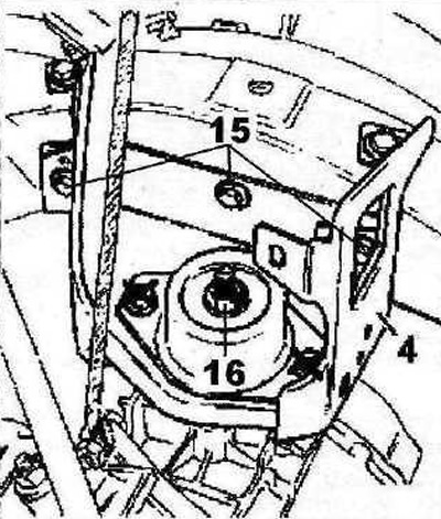
42. Unscrew and replace nuts (2 together with washers 13. as well as gears 14 located between the steering gear and the overframe (see illustration 3.39).
43. Install a support under the steering mechanism 15 from the side of the exhaust manifold (see illustration 3.39).
44. Remove the protective cover 16 (see illustration). The tightening torque for the cover bolts is 18 Nm.
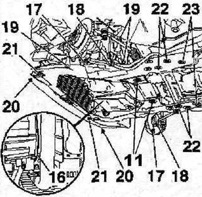
3.44 Remove protective cover 16. Tightening torques: bolts 11 - 90 Nm
45. Unscrew the nuts 17 of the ball bearings securing the transverse suspension arm to the steering knuckle (see illustration 3.44). The tightening torque of the nuts is 40 Nm.
46. Unscrew bolts 18 fastening the anti-roll bar (see illustration 3.44). The tightening torque for the bolts is 50 Nm.
47. Unscrew the bolts 19, 21.22 and 23 fastening the subframe 20 to the body (see illustration 3.44) and remove the subframe.
Tightening torques:
- bolts T9 - 45 Nm;
- bolts 21 and 23 - 65 Nm;
- bolts 22 - 113 Nm.
48. Remove the drive shafts.
49. Raise the gearbox with a hoist or crane by hooking the crane hook to the eye on the gearbox (see illustration).
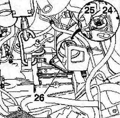
3.49 Lift the gearbox with a hoist or crane, hooking the crane hook to the eye on the gearbox
50. Unscrew the nut 24, remove the washer 25 and remove the gearbox support 26 (see illustration 3.49).
51. Cover the engine protection cover with a piece of cardboard 27 (see illustration).
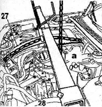
3.51 Cover the engine protection cover with a piece of cardboard 27
52. Mount the engine on a hoist or crane, or install a support beam on the front end «A», to lift the engine and unload its mounts (see illustration 3.51).
53. Unscrew the gearbox mounting bolts 28 (see illustration 3.51) to the engine and carefully remove the box from under the car.
Cars with manual transmission ME5T
54. Disconnect the air duct 1 from the throttle (see illustration).
3.54 Disconnect the air duct 1 from the throttle
55. Remove the air filter 2 (see illustration 3.54).
56. Remove the battery and its tray 3 (see illustration 3.54).
57. Disconnect and move away from the place of work all harnesses, hoses and pipelines connected to the gearbox and preventing its dismantling.
58. Cars with gasoline engines of the ZPJ series. Clamp the throttle body heating hoses with suitable clamps «A» and disconnect the hoses (see illustration).
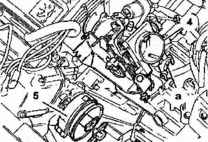
3.58 Clamp the throttle body heating hoses with suitable clamps «A» and disconnect the hoses. Vehicles with ZPJ series gasoline engines
59. Cars with gasoline engines of the ZPJ series (except ZPJ4). Remove throttle 4 (see illustration 3.58)
60. Remove the ignition distributor 5 (see illustration 3.58).
61. Raise the gearbox with a hoist or crane, hooking the crane hook to the eye on the gearbox.
62. Remove the bracket and gearbox mount.
63. Unscrew the central nut 6 of the gearbox support (see illustration). The tightening torque of the nut is 80 Nm.
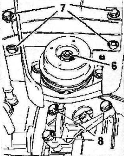
3.63 Unscrew the central nut used for fastening the gearbox support
64. Unscrew the bolts 7 of the support bracket (see illustration 3.63). The tightening torque for the bolts is 30 Nm.
65. Unscrew bolts of fastening of a protective cover of a casing of coupling.
66. Drain gear oil.
67. Remove the drive shafts.
68. Remove downpipe (see illustration).
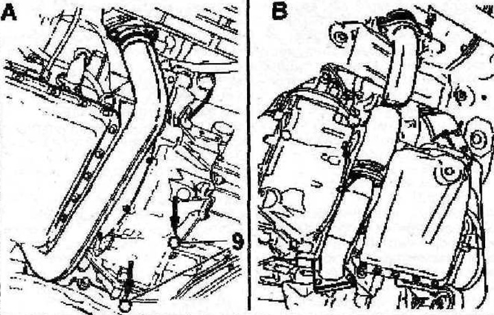
3.68 Remove the downpipe
A - cars with gasoline engines of the ZPJ series
B - cars with petrol engine ZPJ4
69. Remove the protective cover of the clutch cover.
70. Unscrew the lower bolts 9 securing the clutch cover (see illustration 3.68).
71. Remove bolts 8 (see illustration 3.63) fixing the heat-reflecting shield, which closes the starter. The tightening torque for the bolts is 30 Nm.
72. Remove the speedometer sensor.
73. Move the starter away from the place of work without disconnecting it.
74. Install a support beam on the front end to raise the engine and unload the power block supports.
75. Separate the engine and gearbox and move the gearbox away from the engine as far as possible (see illustration).
3.75 Separate the engine from the gearbox and move the gearbox away from the engine as far as possible
76. Lock the flywheel by installing the stop FACOM D86 in the appropriate hole.
77. Remove the clutch and then the flywheel. The tightening torque for the flywheel mounting bolts is 50 Nm.
78. Cover the radiator and adjacent body parts with cardboard to avoid damage when dismantling the gearbox.
79. Make sure the gearbox is securely fastened to the lift (depending on which device - garage lift or crane - is used for dismantling), and carefully remove the box from under the vehicle.
Attention! On vehicles with MG5T manual transmission, to reinstall the box, you must first remove the power unit, and then disconnect the box and the engine.