
Note. Before starting work, read the warning about the dangers and hazards of asbestos dust given at the beginning paragraph 4.
Inspection
Note. If either drive needs to be replaced, BOTH drives should be replaced at the same time. This will ensure uniform and stable braking. You should also install new brake pads.
1. Fully apply the parking brake. Raise the front of the vehicle and securely jack stands under it (see «Lifting and placing the car on supports»). Remove the corresponding front wheel.
2. Rotate the brake disc slowly so that both surfaces of the disc can be checked. If you want better access to the inner surface, remove the brake pads. Light scratches in the contact area with the brake pads are normal, but if serious scratches are found, the disc should be replaced.
3. It's not unusual to see a streak of rust or brake pad dust around the perimeter of the disc; if necessary, these traces can be cleaned. However, if a ledge has formed in the contact area with the brake pads due to increased wear, the thickness of the disc should be measured using a micrometer (pic. 6.3). Measurements should be taken at several locations around the circumference of the disc, on the inner and outer diameters of the contact area with the pads. If at any point the thickness of the disc reaches the minimum prescribed value or even less, the disc should be replaced.
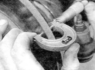
Pic. 6.3. Measure the disc thickness with a micrometer
4. If you think the disc is warped, you can check its runout by following the steps below. Either use a dial indicator, which should be mounted on any convenient fixed point, and slowly rotate the disc around it, or use a feeler gauge to measure the gap between the disc and a fixed element such as a brake caliper support bracket at several places around the circumference of the disc. If the results are at or above the limit value, the disc is warped and should be replaced. However, first you should check the condition of the wheel bearing (see chapter 1A or 1B and/or 10). Also try to remove the disk and install it in place, having previously turned it 180°relative to the hub. If the runout is still high, the disc should be replaced.
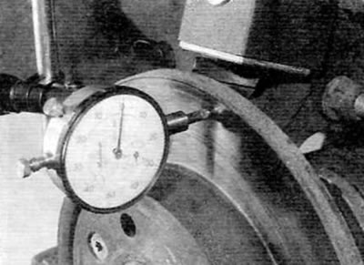
Pic. 6.4. Checking Disc Runout with a Dial Indicator
5. Check the disk for cracks (especially in the area of the holes for the wheel bolts) and any other signs of wear or damage. Replace if necessary.
Removing
6. Remove the brake pads as described in paragraph 4.
7. Turn out two bolts of fastening of a basic arm of a brake support to a rotary fist (pic. 6.7). Remove the support bracket along with the caliper from the disc and knuckle and tie the assembly to the front spring to prevent the brake hose from deforming.
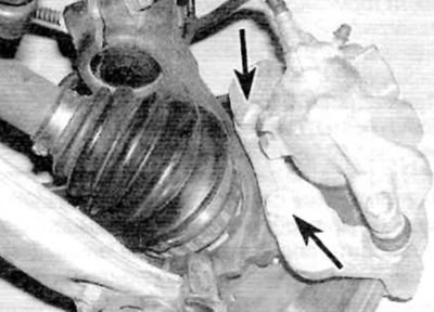
Pic. 6.7. Front caliper support bracket bolts (marked with arrows)
8. Chalk or paint mark the relative position of the disk and hub. Then unscrew all the screws securing the disc to the hub and remove the disc (pic. 6.8, a, b). If the disc does not come off, lightly tap the back of the disc with a plastic mallet to separate it from the hub.
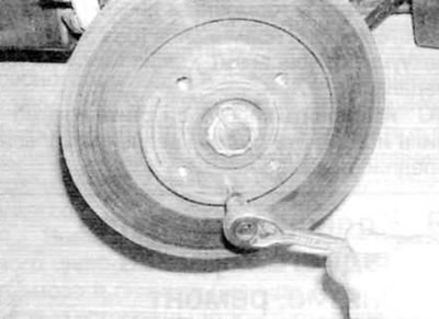
Pic. 6.8, a. Loosen two screws...
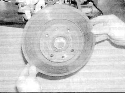
Pic. 6.8b....and remove the front brake disc
Installation
9. Installation is carried out in the reverse order of removal, taking into account the following points:
- A) Make sure the mating surfaces of the disc and hub are clean and flat.
- b) When installing the disc on the hub, align the marks made during removal and securely tighten the disc mounting screws.
- V) If a new disc has been installed, use a suitable solvent to remove the preservation coating from the disc before installing the caliper.
- G) Apply a suitable thread locking compound to the threads of the caliper support bracket mounting bolts and tighten the bolts to the specified torque.
- d) Install the wheel, lower the vehicle and tighten the wheel bolts to the specified torque. Finally, depress the brake pedal several times to restore normal (without vacuum enhancement effect) pedal pressure.