



Caution! Brake pads must be replaced on BOTH rear wheels at the same time. NEVER replace the pads on just one wheel as this may result in uneven braking. Please be aware that dust generated by brake pad wear may contain asbestos, which is hazardous to health. Never blow out this dust with compressed air or inhale it. When working with brakes, use a respirator or cotton-gauze bandage. DO NOT use gasoline or petroleum-based solvents to clean brakes. Use only brake cleaner or denatured alcohol.
1. Remove the brake drum as described in paragraph 7.
2. Remove all dust (resulting from brake wear) from the brake drum, brake shield and shoes. Take all necessary precautions to avoid inhaling it.
3. Measure the friction lining thickness on each brake pad in several places. If the pad wear in any area reaches or exceeds the limit, all four pads should be replaced. The brake pads must be replaced if they become oily, as there is no effective way to degrease contaminated friction linings.
4. If the brake pads are worn unevenly or are oily, find the cause and correct it before reassembling the brake.
5. Mark the installation position of the springs and the spacer bar with the adjuster to facilitate correct assembly.
6. Unhook the end of the lower tension spring from the secondary brake shoe, unhook it from the primary brake shoe and remove the spring (figure 5.6).
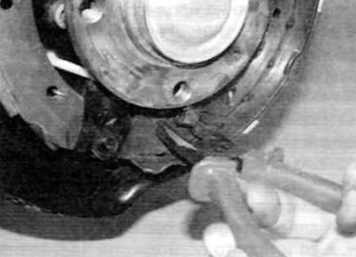
Figure 5.6. Unhook the lower return spring from the secondary brake shoe, unhook it from the primary brake shoe and remove the spring
7. Using pliers, press on the spring cup of the primary brake shoe support post and turn it 90°, while holding the post from the back of the brake shield. After removing the cup, remove the spring and then remove the stand (figure 5.7, a, b). Repeat this procedure for the secondary brake shoe post.

Figure 5.7, a. Press on the spring cup, turn it 50°, while holding the stand from the back of the brake shield
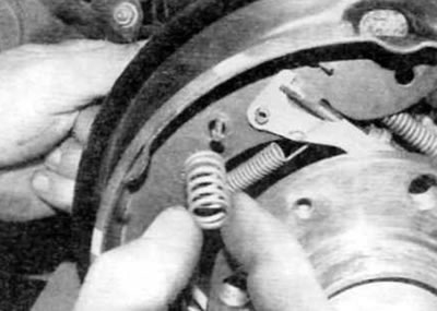
Figure 5.7, b. After removing the cup, remove the spring and then take out the stand
8. Disconnect the parking brake cable end from the lever on the secondary brake shoe (figure 5.8).
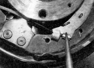
Figure 5.8. Disconnect the parking brake cable end from the lever on the secondary brake shoe
9. Disconnect the adjuster lever spring from the primary brake shoe and adjuster lever, and then remove the lever (figure 5.9, a, b).
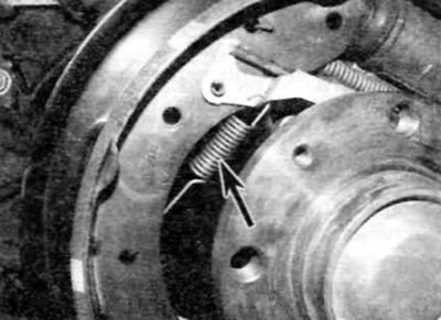
Figure 5.9, a. Disconnect the regulator lever spring (marked with an arrow)...
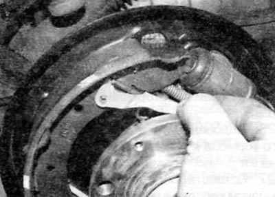
Figure 5.9, b....then remove the regulator lever
10. Remove the brake pads from the lower support pin and release them from the wheel brake cylinder pistons. Spread the lower ends of the pads apart and remove the adjuster bar, the upper tension spring and then the two brake pads.
11. After removing the brake pads, secure the wheel cylinder pistons in the cylinder using a clamp or strong rubber band. Do not press the brake pedal until the brakes are assembled.
12. Remove the forked end of the regulator stand and carefully inspect the assembly for signs of wear or damage. Pay special attention to the threads and knurled adjuster wheel and replace if necessary.
13. Check the condition of all tension springs and replace any springs that show signs of deformation or other damage.
14. Pull back the rubber protective caps and inspect the wheel cylinder for fluid leaks or other damage. Make sure both pistons can move freely. For information on replacing the wheel cylinder if necessary, please refer to paragraph 9.
15. Before installation, clean the brake shield and apply a thin coat of high temperature brake grease or other suitable lubricant to all surfaces of the brake shield that come into contact with the pads, particularly the wheel cylinder pistons and the lower bearing. Avoid contact of lubricant with friction material.
16. Make sure that the parking brake lever stop pin is correctly positioned against the edge of the secondary brake shoe and that the return spring is in its normal position.
17. Connect the upper return spring to the primary and secondary brake shoes (figure 5.17).
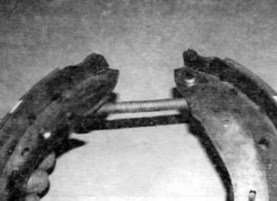
Figure 5.17. Connect the upper return spring to the primary and secondary brake shoes
Original text is located at [www.peugeotbook.ru]
18. Using the adjuster wheel, adjust the adjuster post to its minimum length, then connect the post to the primary brake shoe and the parking brake lever (figure 5.18).
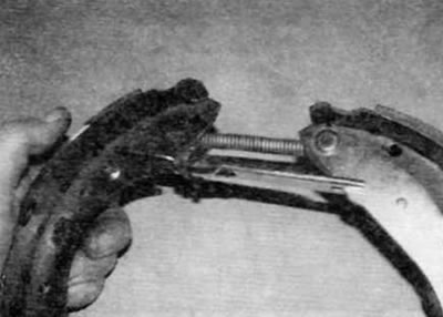
Figure 5.18. Secure the adjuster stand to the primary brake shoe and the parking brake actuator lever
19. Remove the two bolts securing the wheel cylinder to the brake shield. Carefully release the cylinder from the brake shield until the bleed screw comes out of the shield. Move the cylinder up as far as the line will allow to get the maximum possible clearance between the cylinder and the wheel hub.
20. Move the partially assembled brake pad unit to its normal position on the brake shield and insert the brake pads into the grooves on the wheel cylinder pistons (figure 5.20).
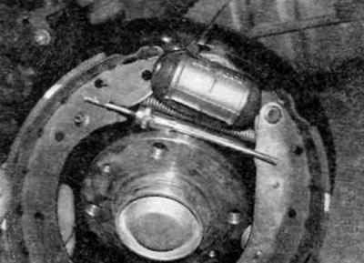
Figure 5.20. Install the partially assembled brake shoe assembly onto the brake shield
21. Pass the lower tension spring behind the lower support and connect one end to the leading brake shoe (figure 5.21).
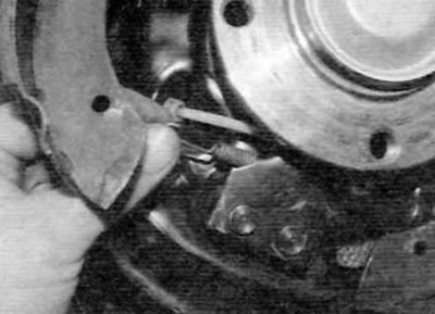
Figure 5.21. Pass the lower return spring behind the support and connect one end to the primary brake shoe
22. Hold the spring on the primary brake shoe and hook the other end of the spring with a screwdriver (figure 5.22).
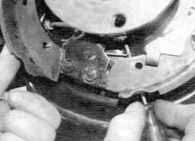
Figure 5.22. Hold the spring on the primary brake shoe and hook the other end of the spring with a screwdriver
23. Pull the spring with a screwdriver to engage it with the edge of the corresponding mounting hole in the secondary brake shoe. Now hook the end of the spring with the tip of a screwdriver and pull it all the way into place (figure 5.23). Please be patient as it may take several attempts due to the limited space behind the secondary brake shoe.

Figure 5.23. Pull the spring to engage it in the mounting hole, then use the tip of a screwdriver to push it all the way into place
24. After connecting the lower spring, install the brake shoes on the lower support and at the same time insert the wheel cylinder into place. Install the wheel cylinder mounting bolts and tighten them securely (figure 5.24).
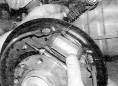
Figure 5.24. Install the brake pads on the lower support and insert the wheel cylinder into its regular place
25. Install the adjuster lever onto the primary brake shoe, ensuring that it is located behind the fork end of the adjuster post. Connect the adjuster lever spring to the lever and primary brake shoe (figure 5.25).
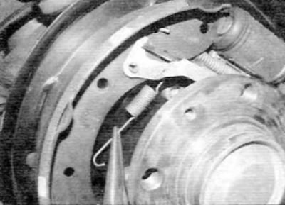
Figure 5.25. Install the adjuster lever onto the primary brake shoe and connect the spring
26. Connect the end of the parking brake cable to the parking brake lever on the secondary brake shoe.
27. Insert the leading brake shoe support post into the brake shield and install the spring onto the post. Hold the strut in place, install the spring cup, and rotate it 90°. Repeat this procedure for the strut on the secondary brake shoe, then press the shoes down to center them relative to the brake shield.
28. Using a screwdriver, turn the adjuster stand wheel to spread the shoes enough so that the brake drum just passes over the shoes.
29. Install the brake drum as described in paragraph 7.
30. Repeat the above procedure on the other rear brake.
31. After replacing both sets of rear brake pads, adjust the clearance between the pads and the drum by depressing the brake pedal several times. While pressing the pedal, have an assistant listen for the sound coming from the rear brake drums to ensure that the adjuster stand is working properly. If everything is OK, a "clicking" sound will come from the regulator post when you press the pedal.
32. Check and, if necessary, adjust the parking brake as described in paragraph 13.
33. Finally, check the brake fluid level in the brake fluid reservoir as described in "Weekly Checks".
34. Keep in mind that new brake pads will not provide full braking performance until. until they get used to it. Be prepared for this and, after replacing the pads, avoid sudden braking for the first few hundred kilometers if possible.