



Table of contents: Heating/ventilation control unit 🠇 Complete heater assembly 🠇 Heater matrix 🠇 Heater blower motor 🠇
Heating/ventilation control unit
1. With the exception of the heater blower motor switch, the heater controls are integral with the heater assembly. The controls are operated by levers pushed through the heater control panel, which engage with the control levers on the heater assembly. Removal of the blower motor switch and the heater illumination bulb is described in Chapter 12.
Complete heater assembly
Removal
2. Drain the cooling system as described in Chapter 1A or 1B.
3. Remove the complete facia assembly as described in Chapter 11.
4. Disconnect the air ducts from each side of the heater assembly (see illustration).
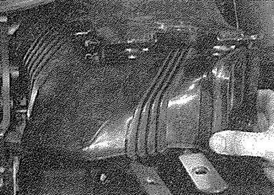
9.4. Disconnect the heater ducts
5. Where applicable, release the speedometer cable from the clips on the rear of the heater assembly. Note the routing of the cable to aid refitting (see illustration).
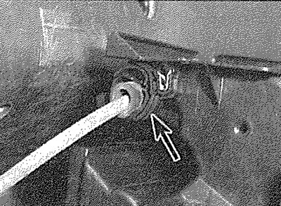
9.5. Speedometer cable clip (arrowed) on rear of heater assembly
6. Working in the engine compartment, disconnect the heater coolant hoses from the heater matrix pipes at the bulkhead. On diesel models, it will be necessary to remove the inlet manifold, as described in Chapter 4D, to gain access (see illustration).
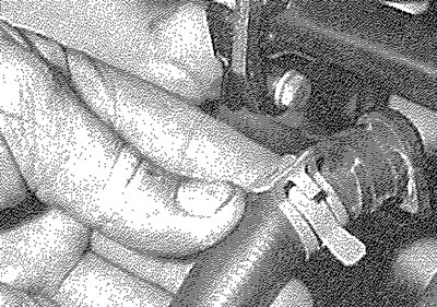
9.6. Disconnecting a heater coolant hose from the matrix pipe
7. Working inside the vehicle, remove the lower heater assembly securing nut (see illustration).
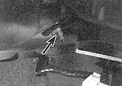
9.7. Lower heater assembly securing nut (arrowed)
8. Carefully pull the heater assembly rearwards from its location, until the heater pipe grommet is free from the bulkhead (see illustration). Withdraw the assembly from the vehicle. Be prepared for coolant spillage from the heater matrix.
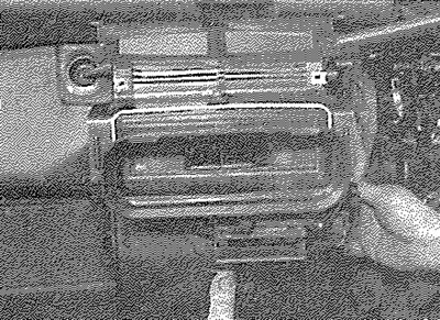
9.8. Withdrawing the heater assembly
Refitting
9. Refitting is a reversal of removal, bearing in mind the following points:
- a) Before refitting the assembly, pull the heater pipe grommet from the pipes and refit the grommet to the bulkhead (see illustration).
- b) As the assembly is refitted, push the heater pipes through the grommet.
- c) On diesel models, refit the inlet manifold as described in Chapter 4D.
- d) Ensure that the speedometer cable is correctly routed behind the heater assembly.
- e) Refit the facia assembly with reference to Chapter 11.
- f) On completion, refill the cooling system as described in Chapter 1A or 1B.
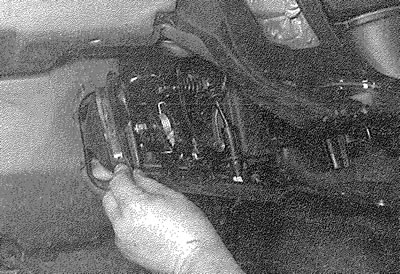
9.9. Fitting the heater pipe grommet to the bulkhead
Heater matrix
Removal
10. Remove the complete heater assembly, as described previously in this Section.
11. Remove the three screws securing the heater matrix to the heater assembly (see illustration).
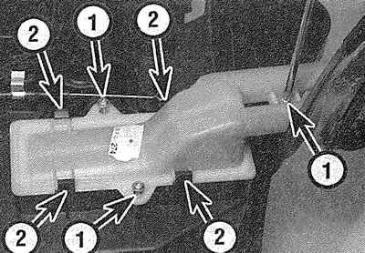
9.11. Remove the securing screws (1) and release the clips (2)...
12. Release the securing clips and withdraw the heater matrix from the heater assembly. Be prepared for coolant spillage (see illustration).
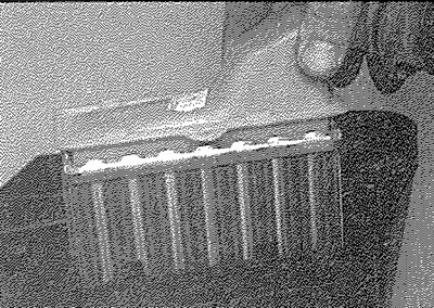
9.12. ... and withdraw the heater matrix
Refitting
13. Refitting is a reversal of removal. Refit the heater assembly as described previously in this Section and refit the facia assembly as described in Chapter 11. On completion, refill the cooling system as described in Chapter 1A or 1B.
Heater blower motor
Removal - right-hand-drive models
14. Remove the complete facia assembly as described in Chapter 11.
15. Disconnect the wiring plug from the heater blower motor.
16. Remove the windscreen wiper arms as described in Chapter 12.
17. Open the bonnet.
18. Remove the securing screw and the two nuts and withdraw the windscreen cowl panel from the scuttle. Note the panel clips around the edge of the windscreen and the front wings.
19. Remove the securing nuts and unclip the plastic cover panel from the right-hand end of the scuttle to expose the heater blower motor securing bolts.
20. Unscrew the securing bolts and lower the heater blower assembly into the vehicle interior.
Refitting
21. Refitting is a reversal of removal. Refit the windscreen wiper arms and the facia assembly as described in Chapters 12 and 11 respectively.
Removal - left-hand-drive models
22. Disconnect the battery negative terminal (refer to "Disconnecting the battery").
23. Working inside the vehicle, remove the two securing screws and withdraw the glovebox assembly.
24. Reach up through the glovebox aperture and disconnect the air trunking from the blower motor casing.
25. On models with air conditioning, working under the facia, unscrew the securing nut and withdraw the motor assembly securing bracket. Recover the spacer if it is loose.
26. Proceed as described in paragraphs 16 to 19 (see illustration).
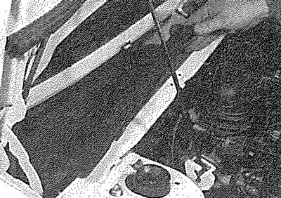
9.26. Removing the heater blower motor cover panel...
27. Unscrew the securing bolts and manipulate the assembly out through the glovebox aperture (see illustration).

9.27. ... to expose the blower motor securing bolts (arrowed) - left-hand-drive model
Refitting
28. Refitting is a reversal of removal.