



Table of contents: General 🠇 Courtesy light 🠇 Glovebox and luggage compartment…🠇 Map reading light 🠇 Instrument panel lights 🠇 Heater control panel illumination…🠇 Switch illumination bulbs 🠇
General
1. Refer to Section 5, paragraph 1.
Courtesy light
2. Carefully prise the light unit from its location in the roof console, then twist the bulbholder anti-clockwise and pull the bulb from the bulbholder (see illustrations).
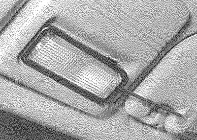
6.2a. Prising the courtesy light from the roof console
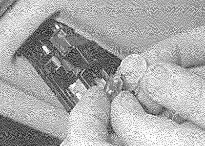
6.2b. The bulb is a push fit in the bulbholder
3. Refitting is a reversal of removal.
Glovebox and luggage compartment lights
4. Carefully prise the light unit from its location, then twist the bulbholder to remove it from the rear of the light unit (see illustration).
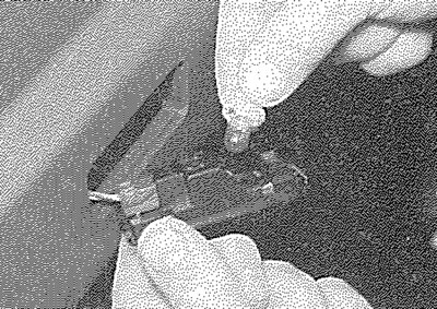
6.4. Removing the luggage compartment light bulbholder
5. The bulb is a push fit in the bulbholder.
6. Refitting is a reversal of removal.
Map reading light
7. Carefully prise the light unit from its location in the roof console (see illustration).
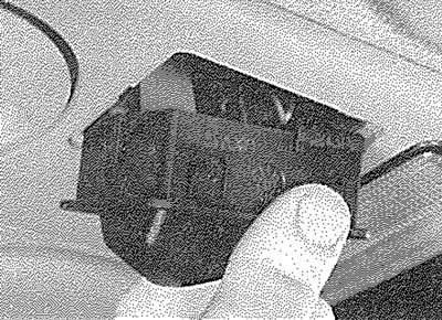
6.7. Prise the map reading light from the roof console...
8. Twist the bulb anti-clockwise to remove it from the light unit (see illustration).
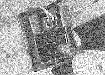
6.8... and remove the bulb
9. The bulb is integral with bulbholder.
10. Refitting is a reversal of removal.
Instrument panel lights
11. Remove the instrument panel as described in Section 9.
12. Twist the relevant bulbholder anticlockwise and withdraw it from the rear of the panel (see illustration).
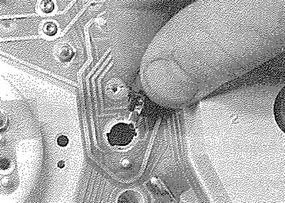
6.12. Removing an instrument panel light bulb
13. All bulbs are integral with their holders.
14. Refit the bulbholder to the rear of the instrument panel, then refit the instrument panel as described in Section 9.
Heater control panel illumination bulb
15. Carefully pull off the blower motor control knob. If necessary, use a pair of pliers, with thin card wrapped round the jaws to protect the switch.
16. Similarly, remove the heater/ventilation control levers.
17. Unscrew the heater control panel securing screw.
18. Withdraw the heater control panel and pull the illumination bulbholder from the rear of the panel.
19. The illumination bulb is a push fit in the bulbholder (see illustration).
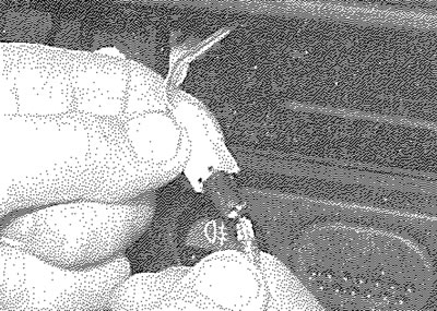
6.19. Removing the heater control panel illumination bulb
20. Fit the new bulb using a reversal of the removal procedure.
Switch illumination bulbs
21. All of the switches are fitted with illuminating bulbs and some are also fitted with a bulb to show when the circuit concerned is operating. The bulbs are an integral part of the switch assembly and cannot be obtained separately. Bulb renewal will therefore require renewal of the complete switch assembly.