



Table of contents: Ignition switch/steering column lock 🠇 Steering column combination switches 🠇 Facia-mounted pushbutton switches 🠇 Heater blower motor switch 🠇 Headlight adjustment and instrument…🠇 Courtesy light switches 🠇 Glovebox and luggage compartment…🠇 Centre console-mounted switches 🠇 Electric window switches 🠇 Electric door mirror adjustment…🠇
Note: Disconnect the battery negative terminal before removing any switch and reconnect the terminal after refitting the switch. Refer to "Disconnecting the battery".
Ignition switch/steering column lock
1. Refer to Chapter 10.
Steering column combination switches
2. Working under the steering column, remove the three steering column shroud securing screws. Unclip and lift off the upper shroud, then withdraw the lower shroud. Note that the lower shroud clips over a metal bracket on the steering column and the shroud must be slid from the bracket before it can be removed. On some models, it may be necessary to remove the steering wheel as described in Chapter 10 in order to allow the steering column shrouds to be removed.
3. Remove the two securing screws (see illustration) and withdraw the relevant switch from the housing on the steering column. Where applicable, note the location of the insulating foam around the switch body.
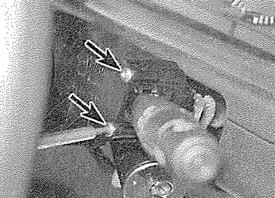
4.3. Remove the securing screws (arrowed)...
4. Disconnect the wiring plug from the rear of the switch (see illustration).
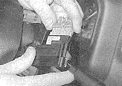
4.4. ... then withdraw the combination switch and disconnect the wiring plug
5. Refitting is a reversal of removal, ensuring that, where applicable, the insulating foam is positioned around the switch as noted before removal.
Facia-mounted pushbutton switches
6. Carefully pull off the blower motor control knob. If necessary, use a pair of pliers, with thin card wrapped round the jaws to protect the switch.
7. Similarly, remove the heater/ventilation control levers.
8. Unscrew the heater control panel securing screw.
9. Withdraw the heater control panel and pull the illumination bulbholder from the rear of the panel
10. Where applicable, remove the radio/cassette player as described in Section 20. If no radio is fitted, unclip the blanking plate from the facia.
11. Depress the retaining lugs at the top and bottom of the radio/cassette player housing, then withdraw the housing from the facia (see illustrations).
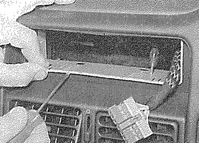
4.11a. Depress the retaining lugs...
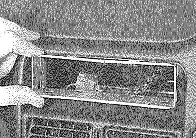
4.11b.... then withdraw the radio/cassette player housing
12. Where applicable, prise out the switch blanking plug (see illustration).
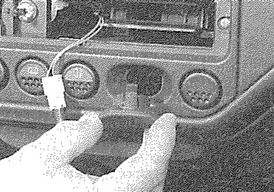
4.12. Removing a switch blanking plug
13. Remove the two ventilation nozzle/switch trim panel securing screws from the heater control panel aperture (see illustration).
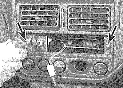
4.13. Remove the ventilation nozzle/switch trim panel securing screws (arrowed)
14. Working through the radio/cassette player housing aperture, unscrew the two ventilation nozzle/switch trim panel securing nuts. Withdraw the panel and disconnect the wiring plug from the heater blower motor switch (see illustration).
Text taken from the website www.PeugeotBook.ru
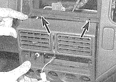
4.14. Withdrawing the ventilation nozzle/switch trim panel. Securing nut studs arrowed
15. Carefully prise the relevant switch out through the front of the facia and disconnect the wiring plug (see illustrations).
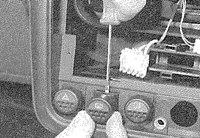
4.15a. Prise out the relevant switch...
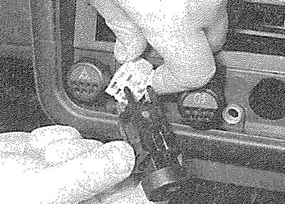
4.15b.... and disconnect the wiring plug
16. Refitting is a reversal of removal
Heater blower motor switch
17. Remove the ventilation nozzle/switch trim panel, as described in paragraphs 6 to 14 inclusive.
18. The switch can be removed from the rear of the panel, after depressing the retaining lugs (see illustrations).
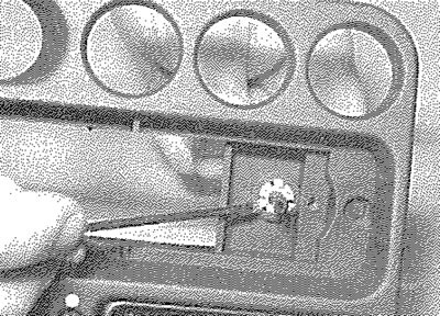
4.18a. Depress the retaining lugs...
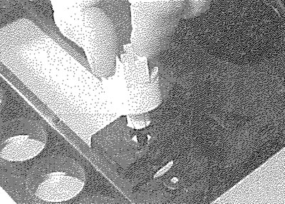
4.18b.... and remove the heater blower motor switch from the ventilation nozzle/switch trim panel
19. Refitting is a reversal of removal.
Headlight adjustment and instrument light dimmer switches
20. Using a suitable flat-bladed screwdriver, carefully prise the relevant switch out of the facia, taking great care not to mark either the panel or the facia. Tilt the switch forward to remove it and disconnect the wiring connector.
21. Refitting is a reversal of removal.
Courtesy light switches
22. Open the door, then prise the rubber gaiter from the switch (see illustration).
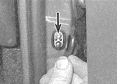
4.22. Prise the rubber gaiter from the courtesy light switch to expose the securing screw (arrowed)
23. Remove the securing screw, then withdraw the switch from the door pillar. Disconnect the wiring connector as it becomes accessible.
24. Refitting is a reversal of removal, but ensure that the rubber gaiter is correctly seated on the switch.
Glovebox and luggage compartment light switches
25. Open the glovebox, or the tailgate, as applicable, then carefully prise the switch from its location and disconnect the wiring connector (see illustration).
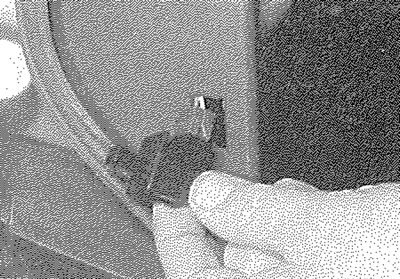
4.25. Removing the luggage compartment light switch
26. Refitting is a reversal of removal.
Centre console-mounted switches
27. Using a suitable flat-bladed screwdriver, carefully prise the switch panel from the centre console (see illustration).
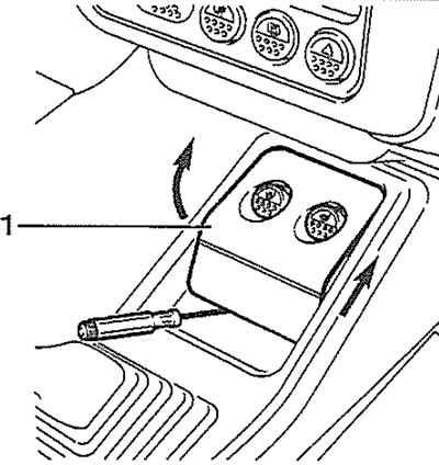
4.27. Prising the switch panel (1) from the centre console
28. Disconnect the switch wiring connectors.
29. Release the securing clips and withdraw the switch from the panel (see illustration).
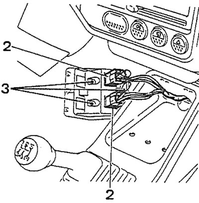
4.29. Centre console-mounted switches (2) and securing clips (3)
30. Refitting is a reversal of removal.
Electric window switches
31. The electric window switches are located in the door pockets on early models, or in the centre console on later models.
32. Carefully prise the switch panel from its location. If necessary, remove the securing screws and withdraw the door pocket first to improve access.
33. Carefully prise the relevant switch from the switch panel and disconnect the wiring plug. Note that on some models, the switch wiring connector may be located inside the door, in which case it will be necessary to remove the inner trim panel and the plastic sealing sheet for access, as described in Chapter 11.
34. Refitting is a reversal of removal. Where applicable, refit the door inner trim panel with reference to Chapter 11 and use a new sealing sheet.
Electric door mirror adjustment switch
35. Carefully prise the switch from the interior door handle trim panel and disconnect he wiring plug. If necessary, prise the interior door handle trim panel from the door first to improve access. Note that on some models, the switch wiring connector may be located inside the door, in which case it will be necessary to remove the inner trim panel and the plastic sealing sheet for access, as described in Chapter 11.
36. Refitting is a reversal of removal. Where applicable, refit the door inner trim panel with reference to Chapter 11 and use a new sealing sheet.