



Fuses
1. Fuses are designed to break a circuit when a predetermined current is reached, in order to protect the components and wiring which could be damaged by excessive current flow. Any excessive current flow will be due to a fault in the circuit, usually a short-circuit (see Section 2).
2. The main fuses are located in the fusebox behind the glovebox on right-hand drive models, or behind a panel in the driver's side facia on left-hand drive models.
3. For access to the fuses, on right-hand drive models, open the glovebox; on left-hand drive models, prise the fusebox cover panel from the facia.
4. On certain models, additional fuses may be located in the auxiliary fuseboxes in the engine compartment. According to model, these auxiliary fuseboxes are either attached to a bracket on the left-hand suspension turret, or situated alongside the battery.
5. A blown fuse can be recognised from its melted or broken wire.
6. To remove a fuse, first ensure that the relevant circuit is switched off.
7. Using the plastic tool provided in the fusebox, pull the fuse from its location (see illustration).
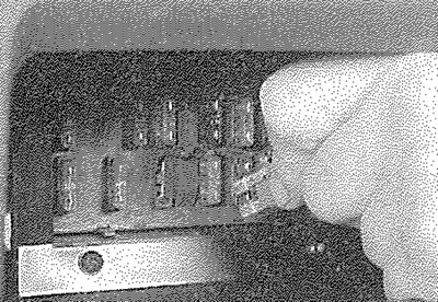
3.7. Removing a fuse using the plastic tool
8. Spare fuses are provided in the blank terminal positions in the fusebox.
9. Before renewing a blown fuse, trace and rectify the cause and always use a fuse of the correct rating. Never substitute a fuse of a higher rating, or make temporary repairs using wire or metal foil; more serious damage, or even fire, could result
10. Note that the fuses are colour-coded as follows. Refer to the wiring diagrams for details of the fuse ratings and the circuits protected:
| Colour | Rating |
| Orange | 5A |
| Red | 10A |
| Blue | 15A |
| Yellow | 20A |
| Clear or White | 25A |
| Green | 30A |
11. The radio/cassette player has an in-line fuse located in the wiring behind the unit.
Relays
12. A relay is an electrically-operated switch, which is used for the following reasons:
- a) A relay can switch a heavy current remotely from the circuit in which the current is flowing, allowing the use of lighter-gauge wiring and switch contacts.
- b) A relay can receive more than one control input, unlike a mechanical switch.
- c) A relay can have a timer function - for example, the intermittent wiper relay.
13. Most of the relays are located at the rear of the main fusebox (remove the securing screws and pull the fusebox forwards to improve access). The rear wiper motor relay is located in the tailgate, behind the tailgate trim panel. On some models, additional engine-related relays are located in an auxiliary fusebox mounted on the left-hand side of the engine compartment (see illustrations).
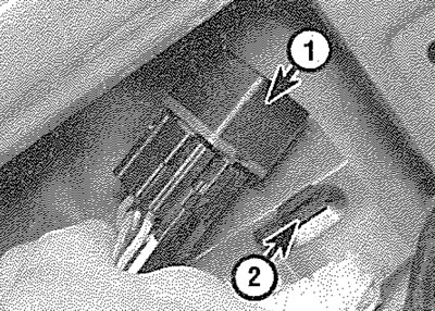
3.13a. Rear wiper motor relay (1) and securing clip (2)
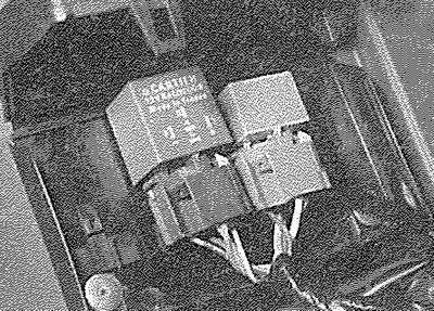
3.13b. Relays located in auxiliary fusebox - diesel model shown
14. If a circuit or system controlled by a relay develops a fault and the relay is suspect, operate the system. If the relay is functioning, it should be possible to hear it "click" as it is energised. If this is the case, the fault lies with the components or wiring of the system. If the relay is not being energised, then either the relay is not receiving a main supply or a switching voltage, or the relay itself is faulty. Testing is by the substitution of a known good unit, but be careful - while some relays are identical in appearance and in operation, others look similar but perform different functions.
15. To remove a relay, first ensure that the relevant circuit is switched off. The relay can then simply be pulled out from the socket and pushed back into position.