



Table of contents: General 🠇 Headlight 🠇 Front sidelight 🠇 Front direction indicator - pre-July…🠇 Front direction indicator - July…🠇 Front direction indicator side…🠇 Front direction indicator side…🠇 Front driving lights/foglights -…🠇 Front driving lights/foglights -…🠇 Rear light cluster - pre-July 1996…🠇 Rear light cluster - July 1996…🠇 High-level stoplight 🠇 Rear number plate light 🠇
General
1. Whenever a bulb is renewed, note the following points:
- a) Disconnect the battery negative terminal before starting work. Refer to "Disconnecting the battery".
- b) Remember that, if the light has just been in use, the bulb (and its holder) may be extremely hot.
- c) Always check the bulb contacts and holder, ensuring that there is clean metal-to-metal contact between the bulb and its live contact and earth. Clean off any corrosion or dirt before fitting a new bulb.
- d) Wherever bayonet-type bulbs are fitted, ensure that the live contact bear firmly against the bulb contact.
- e) Always ensure that the new bulb is of the correct rating and that it is completely clean before fitting it; this applies particularly to headlight/foglight bulbs (see following paragraphs).
Headlight
2. Open the bonnet, then working at the rear of the headlight assembly, release the securing clip and lift up the headlight rear cover (see illustration). On later models, twist the headlight rear cover anti-clockwise to remove it from the headlight.
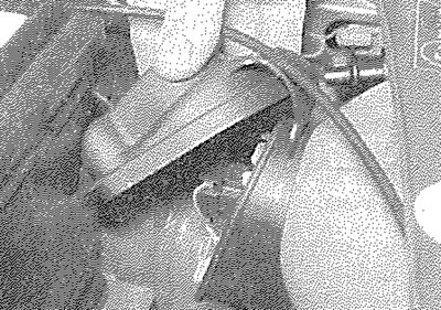
5.2. Lift up or twist off the headlight rear cover...
3. Pull the wiring plug from the rear of the bulb (see illustration).
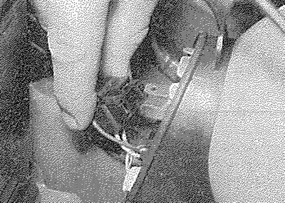
5.3. ... pull the wiring plug from the bulb...
4. Press together the ends of the bulb retaining clip and release it from the rear of the light (see illustration).
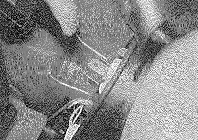
5.4. ... release the retaining clip...
5. Withdraw the bulb (see illustration).
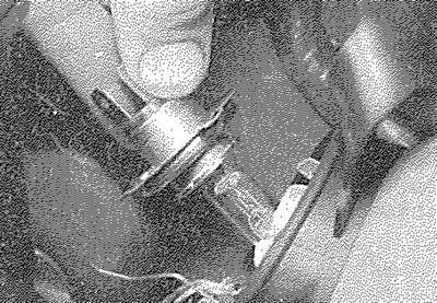
5.5. ... and withdraw the bulb
6. When handling the new bulb, use a tissue or clean cloth, to avoid touching the glass with the fingers; moisture and grease from the skin can cause blackening and rapid failure of this type of bulb.
7. Install the new bulb, ensuring that its locating tabs are correctly located in the light unit cut-outs. Secure the bulb in position with the retaining clip and reconnect the wiring connector plug.
8. Refit the headlight rear cover, ensuring that it is correctly seated on the rear of the light unit
Front sidelight
9. Proceed as described in paragraphs 2 and 3.
10. Twist the bulbholder through quarter of a turn and withdraw it from the headlight housing.
11. Pull the push-fit bulb from the bulbholder (see illustration).
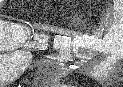
5.11. Removing a sidelight bulb
12. Fit the new bulb using a reversal of the removal procedure, ensuring that the bulbholder sealing ring is in good condition.
Front direction indicator - pre-July 1996 models
13. Open the bonnet and working at the front wing behind the direction indicator light, release the light unit retaining spring from the hole in the body panel (see illustration).
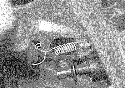
5.13. Release the front direction indicator light unit retaining spring...
14. Withdraw the light unit forwards from the front wing (see illustration).
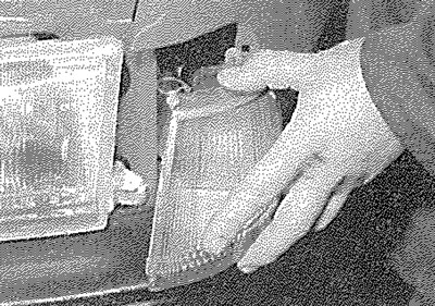
5.14. ... withdraw the light unit...
15. Twist the bulbholder anti-clockwise to release it from the rear of the light unit (see illustration).
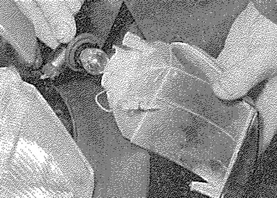
5.15. ... remove the bulbholder...
16. The bulb is a bayonet fit in the bulbholder and can be removed by pressing it and twisting in an anti-clockwise direction (see illustration).
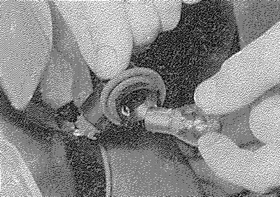
5.16. ... then withdraw the bulb
17. Refitting is a reversal of removal, bearing in mind the following points:
- a) Ensure that the bulbholder sealing ring is in good condition.
- b) When refitting the light unit, ensure that the lugs on the rear of the unit engage with the corresponding holes in the body panel.
- c) Ensure that the light unit retaining spring is correctly located in the hole in the body panel.
Front direction indicator - July 1996 models onward
18. Access to the bulbs is from under the front wheel arch. To change the left-hand bulb, turn the steering onto full right lock and to full left lock for the right-hand bulb.
19. Reach up under the wheel arch and open the access flap (see illustration).
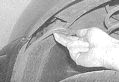
5.19. On later models, reach up under the wheel arch and open the access flap...
20. Working through the aperture in the wheel arch liner, twist the bulbholder anti-clockwise to release it from the rear of the light unit (see illustration).
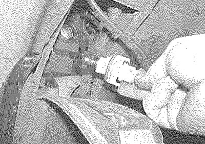
5.20. ... remove the bulbholder...
21. The bulb is a bayonet fit in the bulbholder and can be removed by pressing it and twisting in an anti-clockwise direction (see illustration).
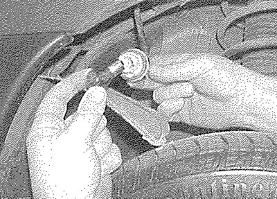
5.21. ... then withdraw the bulb
22. Refitting is a reversal of removal, ensuring that the bulbholder sealing ring is in good condition and the access flap is securely closed.
Front direction indicator side repeater - pre-July 1996 models
23. Remove the light unit, as described in Section 7.
24. Pull the bulbholder from the rear of the light unit. The bulb is a push fit in the bulbholder (see illustrations).
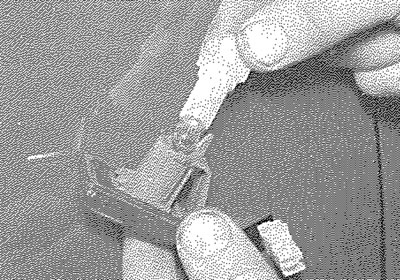
5.24a. Pull the bulbholder from the direction indicator side repeater light...
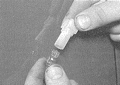
5.24b.... then pull the bulb from the bulbholder
Front direction indicator side repeater - July 1996 models onward
25. Pull the rear part of the transparent cover to release the assembly.
26. Support the connector, turn the transparent cover anti-clockwise then pull the bulb out of its holder (the bulb is a push-fit).
27. Refitting is a reversal of the removal procedure.
Front driving lights/foglights - pre-July 1996 models
28. Working at the front of the light unit, remove the two securing screws and withdraw the glass, surround and reflector assembly.
29. Disconnect the bulb wiring connector.
30. Release the spring clip and remove the bulb from the rear of the light unit.
31. When handling the new bulb, use a tissue or clean cloth, to avoid touching the glass with the fingers; moisture and grease from the skin can cause blackening and rapid failure of this type of bulb. If the glass is accidentally touched, wipe it clean using methylated spirit.
32. Install the new bulb, ensuring that its locating tabs are correctly located in the light unit cut-outs. Secure the bulb in position with the retaining clip and reconnect the wiring connector.
33. Refit the glass, surround and reflector assembly and tighten the securing screws.
Front driving lights/foglights - July 1996 models onward
34. Working under the front bumper twist the bulbholder anti-clockwise to release it from the rear of the light unit, then remove the bulb from the holder.
35. When handling the new bulb, use a tissue or clean cloth, to avoid touching the glass with the fingers; moisture and grease from the skin can cause blackening and rapid failure of this type of bulb. If the glass is accidentally touched, wipe it clean using methylated spirit.
36. Install the new bulb, then refit the bulbholder to the light unit.
Rear light cluster - pre-July 1996 models
37. Remove the light unit as described in Section 7.
38. Remove the two securing screws from the lens (see illustration).
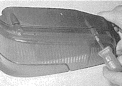
5.38. Remove the two securing screws...
39. Slightly lift the top of the lens from the light unit, then release the clips at the lower edge of the lens (see illustration). Withdraw the lens from the light unit.
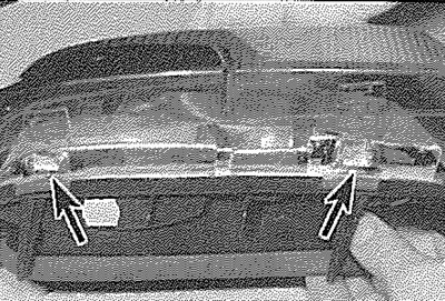
5.39. ... then release the securing clips (arrowed) and withdraw the lens from the rear light cluster
40. The bulbs are a bayonet fit in the bulbholder unit and can be removed by pressing and twisting in an anti-clockwise direction (see illustration). Note that the stop/tail light has offset pins, to ensure correct installation.
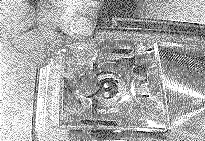
5.40. Removing a bulb from the rear light cluster
41. Refitting is a reversal of removal, ensuring that the lens is located correctly in the seal. Refit the light unit with reference to Section 7.
Rear light cluster - July 1996 models onward
42. Remove the light unit as described in Section 7.
43. Release the bulbholder from the light unit by squeezing the retaining tabs (see illustration).
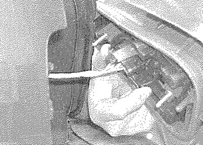
5.43. On later models, release the bulbholder by squeezing the tabs...
44. The bulbs are a bayonet fit in the bulbholder (see illustration).
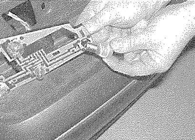
5.44. ... then withdraw the bulb
45. Refitting is a reversal of the removal procedure. Refit the light unit with reference to Section 7.
High-level stoplight
46. Using a small screwdriver, depress the retaining tags on the side of the light unit cover and remove the cover (see illustration).
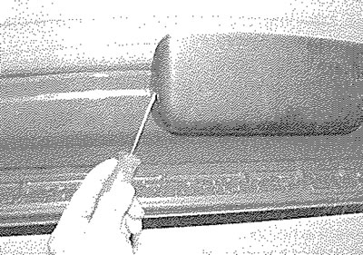
5.46. Depress the retaining tags and remove the high-level stoplight cover
47. Release the bulbholder from the light unit by squeezing the retaining tabs (see illustration).
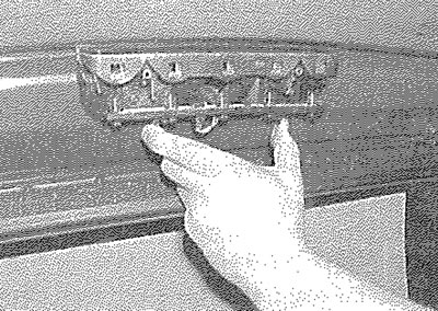
5.47. Squeeze the retaining tabs to remove the bulbholder...
48. The bulbs are a push-fit in the bulbholder (see illustration).
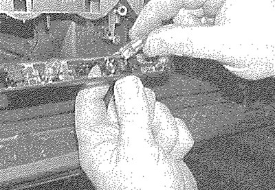
5.48. ... then remove the push-fit bulbs from the holder
49. Refitting is a reversal of the removal procedure.
Rear number plate light
50. Using a small flat-bladed screwdriver, carefully prise out the light lens to gain access to the bulb.
51. The bulb is a push fit in the light unit (see illustration).
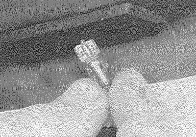
5.51. Removing a rear number plate light bulb
52. Refitting is a reversal of removal.